Professional cable manufacturer

Professional cable manufacturer
7 installation methods from direct burial to cable tray, with selection matrix & pre-installation checklist
While there are many cable laying techniques, the four most common are: direct burial, duct/conduit installation, cable trench/tunnel installation, and cable tray installation. Below is a detailed breakdown of all major methods and their technical requirements.
Reference: GB 50217-2018 §5.2 | GB 50168-2018 §5
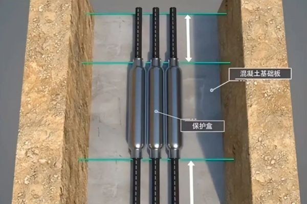
Direct burial involves laying cables directly into the ground. It is the most cost-effective method, ideal for open areas such as rural land, roadsides, and building perimeters. The downside is difficulty in maintenance and future expansion.
0.7m in general areas, 1.0m in agricultural land. If depth requirements cannot be met, a protective layer of 100mm fine sand or soft soil must be placed both above and below the cable, covered with cement slabs or bricks extending 50mm beyond each cable side. Backfill material must be free of stones, bricks, and debris.0.5m.150mm above ground.When crossing roads or railways, direct buried cables must be installed in protective conduits extending at least 1m beyond the roadbed on each side. For reliable performance, consider Sorivo armoured power cables — their double steel tape armour provides excellent protection against mechanical stress during backfilling and ground settlement.
Reference: GB 50217-2018 §5.3 | GB 50168-2018 §6
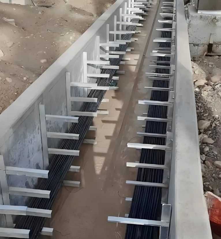
Cable trenches and tunnels are widely used in industrial plants, substations, and other cable-dense areas. They allow centralized cable management and convenient walk-in inspection.
0.5% (per GB 50217-2018 §5.3.2).150m.35mm; between HV and LV power cables: minimum 150mm.Some references cite a cable trench drainage slope of 0.1%. In actual engineering practice, this is far too shallow for effective drainage. Per GB 50217-2018, the drainage gradient should be no less than 0.5%. In corrosive or high-rainfall regions, a gradient of 1% is recommended.
Reference: GB 50054-2011 §7.2 (Low-Voltage Distribution Design Code)
This method suspends cables from a steel wire rope (messenger wire) spanning between poles. It is occasionally used for temporary supplies or industrial cross-site runs but has largely been replaced by cable tray and trunking in modern installations.
200mm from the pole top.20mm of galvanized iron wire to prevent strand unraveling.750mm intervals using a suspension trolley.Aerial catenary installation is still found in temporary industrial supply and construction site applications. For permanent installations, cable tray or ladder systems are preferred for better aesthetics and easier maintenance.
Reference: GB 50217-2018 §5.4 | GB 50168-2018 §5.4
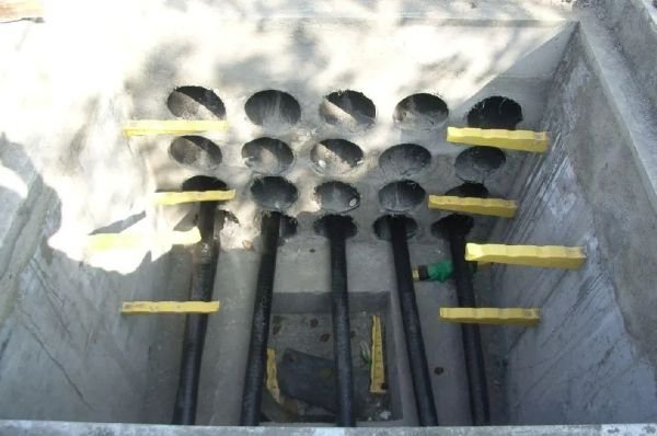
Duct installation routes cables through pre-laid underground pipes. It is widely used in urban roads, sidewalks, and road crossings — anywhere cables may need future replacement without excavation.
50m. Manhole covers should be cast iron, raised above ground level, with integrated sump drainage.<30m: straight section ≥ 2× cable OD; one bend ≥ 2.5×; two bends ≥ 3×. For runs ≥30m: straight section ≥ 3× cable OD.Duct bend radii must not be less than the cable's minimum permissible bending radius (typically 15–20× cable OD for power cables). Sorivo XLPE insulated power cables offer excellent bending performance, making duct installation easier and safer.
Reference: GB 50217-2018 §6 | GB 50168-2018 §5.5
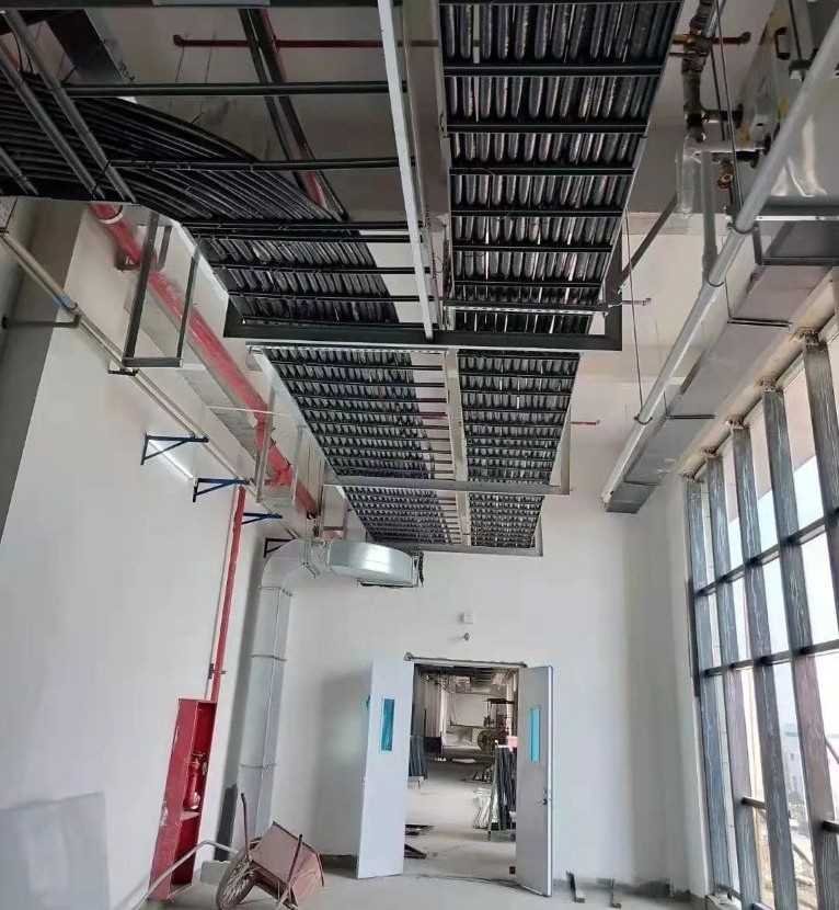
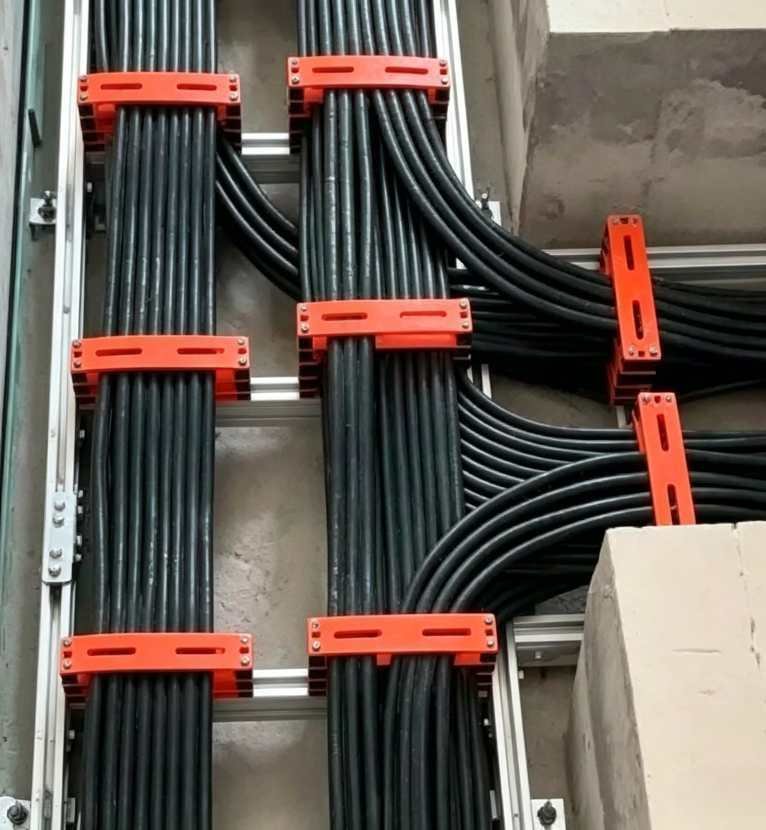
Cable tray installation is the most widely used method in modern commercial and industrial projects. It provides clear cable segregation, easy expansion, and straightforward maintenance.
200mm; power cable trays: ≥ 300mm; HV and LV cable trays: ≥ 500mm (may be reduced to 300mm with shielding). Clearance above tray to ceiling or obstructions: ≥ 300mm.100mm gap.40% of tray cross-section; control cables: ≤ 50%.When power and signal cables share the same tray route, pay special attention to electromagnetic interference (EMI). Maintain ≥ 500mm separation wherever possible, or use shielded control/ instrumentation cables. Sorivo screened control cables provide excellent EMI rejection for reliable signal transmission in mixed cable environments.
Reference: GB 50217-2018 §5.6
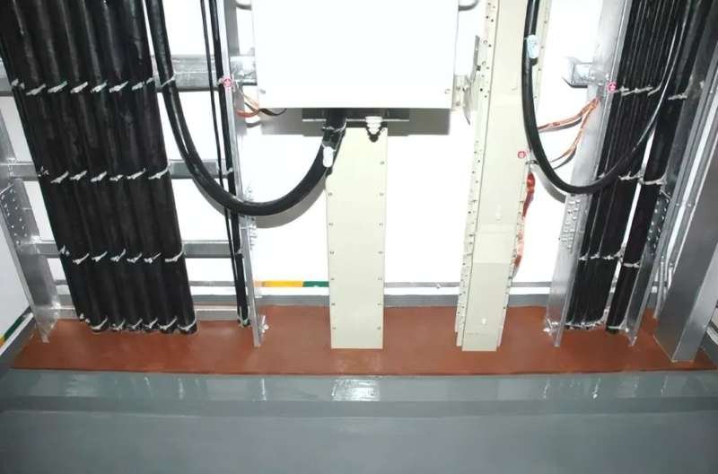
Electrical shafts (risers) are widely used in high-rise buildings for vertical cable routing between floors.
Fire stopping is critical in electrical shafts. All cable penetrations between floors must be fire-sealed with approved firestop materials to prevent vertical flame spread.
Reference: GB 50054-2011 §7.2
Surface mounting along walls and ceilings is the most flexible wiring method, often used in retrofits and small-scale electrical projects.
For outdoor surface mounting, use UV-resistant cable sheaths or run cables in conduits. Indoor surface mounting in occupied spaces should use Sorivo low-smoke halogen-free (LSZH) building wires — they emit minimal toxic smoke in a fire, making them ideal for commercial and public buildings.
Choosing the right installation method for your project? The table below compares seven methods across six key dimensions.
| Method | Typical Application | Advantages | Limitations | Suitable Cable Types | Reference Standard |
|---|---|---|---|---|---|
| Direct Burial | Rural areas, roadsides, building perimeters | Lowest cost, fast installation | Difficult to inspect/modify, soil corrosion risk | Armoured power cables (e.g. YJV22, YJLV22) | GB 50217 §5.2 |
| Cable Trench / Tunnel | Industrial plants, substations, cable-dense areas | Easy inspection, good heat dissipation, centralized routing | High civil cost, water accumulation risk | Standard power & control cables | GB 50217 §5.3 |
| Aerial Catenary | Industrial cross-site, temporary supply | No ground space used, fast deployment | Poor aesthetics, wind load vulnerability, largely superseded | Lightweight & wire-armoured cables | GB 50054 §7.2 |
| Duct / Conduit | Urban roads, sidewalks, road crossings | Excellent protection, easy cable replacement | Poor heat dissipation, reduced ampacity, higher cost | Plastic-sheathed cables, XLPE cables | GB 50217 §5.4 |
| Cable Tray | Commercial buildings, factories, tunnels | Clear segregation, easy expansion, professional appearance | Requires space, needs firestopping | Power cables, control cables, instrumentation cables | GB 50217 §6 |
| Electrical Shaft | High-rise building vertical risers | Saves floor space, centralized vertical routing | Strict fireproofing needed, difficult installation | Flame-retardant power & control cables | GB 50217 §5.6 |
| Surface Mounted | Interior retrofits, small-scale projects | Maximum flexibility, simple installation | Visual impact, mechanical damage risk | Building wires (BV, BVR, RVV, etc.) | GB 50054 §7.2 |
For long outdoor runs → direct burial with armoured cable. Urban utility corridors → duct bank + cable tray combination. High-rise buildings → shaft riser + horizontal tray. Chemical plants → cable trench with corrosion-resistant coating. Need help with cable selection? Visit the SORIVO product center for detailed specifications and datasheets.
Proper preparation is the key to a safe and compliant cable installation. Use this checklist as a site inspection reference.
0°C; pre-warm cables if below)Below 0°C, XLPE and PVC cables become stiff and their bending radius increases significantly. If cold-weather installation is unavoidable, warm the cable drums in a heated room (≥ 24 hours) or use approved warming methods to raise the cable surface temperature to 5–10°C before handling.
Per GB 50217-2018 §5.2.1, direct-buried cables must have armouring and corrosion protection. The armour layer (typically steel tape or steel wire) provides protection against:
Non-armoured cables (e.g. standard YJV) are not suitable for direct burial. Sharp stones and debris in backfill can easily penetrate the sheath. If non-armoured cable must be used for a short crossing, install it inside a protective conduit.
HV cables (≥ 10kV) and LV cables (0.6/1kV) should not share the same tray layer. They must be installed on separate layers with a vertical spacing of ≥ 300mm.
If same-layer installation is unavoidable, a solid metal partition must be installed between cable groups, with voltage ratings clearly labelled on each side. For signal and instrumentation cables, maintain ≥ 500mm separation from power cables, or use shielded/armoured signal cables.
Reference: GB 50217-2018 §6.2.1
Cables in ducts are enclosed in a poorly ventilated space. Heat generated by conductor losses cannot dissipate as effectively as in open air, so ampacity must be derated. The derating factor depends on:
Typical derating factors:
0.70–0.800.50–0.65For precise values, calculate per IEC 60287 or refer to the ampacity tables in GB 50217. A 15–20% ampacity margin in preliminary design is good practice.
The recommended sequence from top to bottom is:
0.6/1kV)6kV and above)This arrangement places the highest-energy cables at the bottom, so that in the event of a fault, arc damage is contained below other cables. Weak-current cables also benefit from maximum distance to the EMI source. Reference: GB 50217-2018 §5.3.5.
Four key criteria for surface-mounted indoor cables:
2m from floor level require additional mechanical protection — either conduit or armoured cable.The Sorivo LSZH building wire series meets both flame retardance and zero-halogen requirements for demanding indoor applications.
Need expert cable selection advice for your project? Browse SORIVO's full cable range or contact our technical team for a free installation consultation and cable quotation.
Cable laying is a critical phase of any electrical installation. Choosing the right method requires careful consideration of site environmental conditions, cable characteristics, safety requirements, and project budget. Whether using direct burial, trench, duct bank, tray, or surface mounting, strict adherence to applicable standards — including GB 50217, GB 50168, and GB 50054 — is essential for long-term safety and reliability.
This article references GB 50217-2018 (Code for Design of Cables of Electric Power Engineering), GB 50168-2018 (Code for Installation and Acceptance of Cable Lines), and other applicable standards for informational purposes. For actual engineering design, always refer to the latest edition of relevant codes and project-specific drawings.