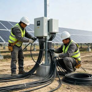
Proper solar cable installation is just as critical as selecting the right cable. Even the highest-quality PV wire can fail prematurely if installed incorrectly—leading to system downtime, fire hazards, and costly repairs. This guide covers key installation practices to ensure your photovoltaic system operates safely and reliably for decades.
1. Pre-Installation Checklist
Before pulling any cable, verify the following:
Item
Requirement
Why It Matters
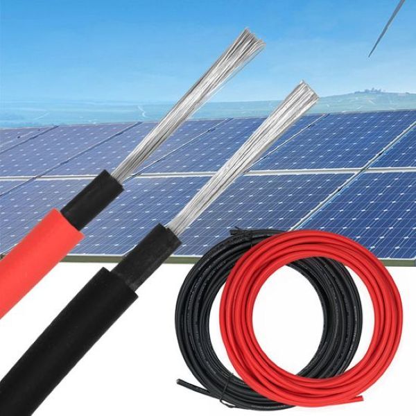
Cable Type
PV1-F or H1Z2Z2-K (DC side)
Designed for UV exposure and wet conditions.
Voltage Rating
Match system voltage (600V or 1500V DC)
Undersized voltage rating causes insulation breakdown.
Temperature Rating
Minimum 90°C (wet/dry)
Rooftop temperatures can exceed 70°C in summer.
Certification
TÜV, UL 4703, or IEC 62930
Ensures compliance with fire and weathering standards.
2. Cable Routing and Mechanical Protection
A. Avoid Sharp Bends and Edges
Minimum Bend Radius: Maintain at least 4–6× the cable outer diameter for fixed installations, and 8–10× for moving flex applications.
Edge Protection: Use grommets, conduits, or cable trays when passing through metal frames, roof penetrations, or sharp structural edges. Unprotected cables can develop insulation cuts from thermal expansion and wind vibration.
B. Proper Support and Securing
Cable Ties: Use UV-stabilized, black nylon cable ties rated for outdoor use. Standard white ties become brittle and fail within 1–2 years under sunlight.
Spacing: Secure cables every 40–50 cm along horizontal runs and every 60–80 cm vertically. Avoid overtightening—compressed insulation can create hot spots.
Avoid Direct Roof Contact: Where possible, elevate cables using stainless steel cable clips or PV cable hangers to prevent water pooling and debris accumulation.
C. Conduit Selection
Environment
Recommended Conduit
Notes
Exposed Rooftop
Rigid Metal Conduit (RMC) or UV-resistant PVC
Provides mechanical protection and UV shielding.
Underground
Schedule 40/80 PVC or HDPE
Must be buried at required depth per local code.
High-Temperature Areas
Metallic conduit with expansion joints
Prevents warping from thermal cycling.
3. Connector and Termination Best Practices
A. MC4 Connector Assembly
Use Manufacturer-Matched Pairs: Mixing MC4 connectors from different brands can result in poor contact resistance and moisture ingress. Always use connectors from the same manufacturer and series.
Crimping Tool Calibration: Use a calibrated, brand-specific crimping tool. Improper crimps are the leading cause of connector overheating and arc faults.
Torque Requirements: Follow manufacturer-specified torque values for cable glands. Over-tightening cracks the housing; under-tightening allows water entry.
B. Avoid These Common Connector Mistakes
Mistake
Consequence
Correct Practice
Cutting cables to exact length without slack
Stress on connectors from thermal expansion
Leave a service loop of 15–20 cm at each connection point.
Connectors resting in standing water
Corrosion and insulation breakdown
Elevate connectors off the roof surface using cable clips.
Unmated connectors left exposed
Water ingress and oxidation
Always cap unused connectors with IP68-rated sealing caps.
4. Cable Management for Long-Term Reliability
A. Separation of AC and DC Circuits
Maintain a minimum separation distance of 20–30 cm between AC and DC cables.
If crossing is unavoidable, do so at 90-degree angles and use shielded cable or metallic conduit dividers.
Reason: AC electromagnetic fields can induce noise in DC communication lines (e.g., RS485 for module-level monitoring).
B. UV and Weather Protection
All outdoor cables must be rated for direct sunlight exposure. Look for “Sunlight Resistant” or “UV Resistant” markings.
Warning: Cables with faded printing within the first year indicate insufficient UV stabilizers—replace immediately.
C. Labeling and Documentation
Label Content
Location
Purpose
String ID
Combiner box and array end
Simplify troubleshooting and maintenance.
Polarity (+ / -)
Both ends of each DC run
Prevents reverse polarity connection.
Voltage Warning
Inverter and disconnect switches
Safety compliance (NEC 690 requirement).
5. Post-Installation Testing
Complete these tests before commissioning the system:
Test
Method
Acceptable Range
Insulation Resistance
Megohmmeter at 500V or 1000V DC
> 20 MΩ (dry); > 1 MΩ (wet)
Continuity
Multimeter
< 1 Ω per 100m run
Polarity Check
DC voltmeter
Match string design (+ / -)
Voltage Drop
Measure at array vs. inverter
< 3% of system voltage
6. Common Installation Errors and How to Avoid Them
Error
Risk
Prevention
Running cables over sharp roof edges
Insulation cuts, ground faults
Install edge guards or conduit elbows.
Coiling excess cable tightly
Inductive heating, reduced ampacity
Use figure-eight or large-radius loops.
Mixing aluminum and copper conductors
Galvanic corrosion
Use bimetallic connectors (Cu/Al rated).
Ignoring derating in conduit
Overheating, insulation failure
Apply NEC Chapter 9 fill and derating tables.
7. Maintenance Schedule for Installed Cables
Frequency
Action
Every 6 months
Visual inspection for cable damage, connector discoloration, and loose ties.
Annually
Torque check on all accessible terminations.
Every 2 years
Insulation resistance testing (megger test).
After severe weather
Inspect for wind damage, water ingress, or animal chewing.
Conclusion
Proper installation practices are the foundation of a safe, high-performing solar system. By following these guidelines—maintaining bend radii, using UV-rated securing materials, performing correct terminations, and conducting post-installation testing—you can extend cable service life to 25+ years and minimize system downtime.
Need technical support for your PV cable installation? Contact Soarwit for project-specific guidance and certified cable solutions compliant with IEC 62930, UL 4703, and TÜV standards.