Professional cable manufacturer

Professional cable manufacturer
Standards referenced: TÜV 2PfG 2693/03.23 / UL 9540 / UL 9540A / NFPA 855 / T/CNESA 1003-2020 / IEC 60228 / IEC 60332-1-2 / IEC 60754-1/2 / IEC 60502-1 / IEC 62930
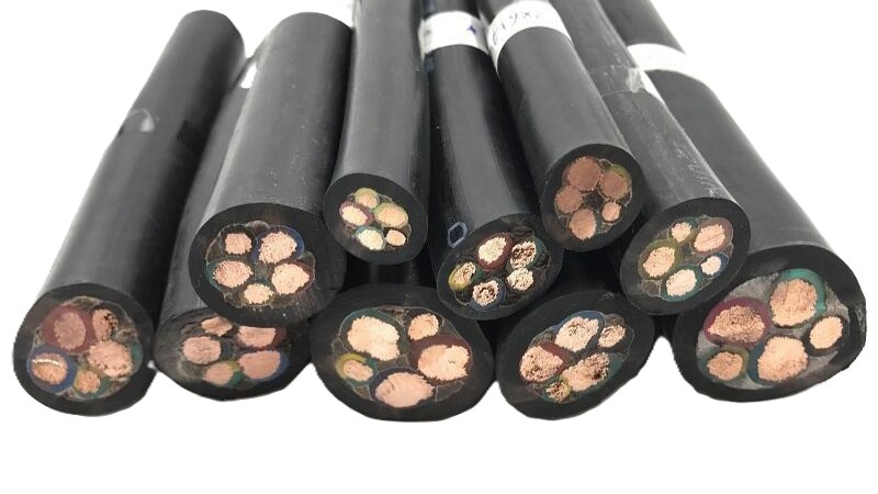
The BESS industry is growing fast — maybe too fast to keep up with the details. And one detail that keeps getting overlooked is the cables. We crossed 250 GW globally in 2025, overtaking pumped hydro storage for the first time. Annual installations hit 100 GW, up 51% year on year. By 2034, Wood Mackenzie projects 1,545 GW of cumulative capacity — nearly six times today's numbers.
This explosive growth comes with a shift in system architecture. The industry standard has moved decisively from 600V DC to 1500V DC for utility-scale BESS, driven by lower balance-of-system costs, higher round-trip efficiency, and reduced cable cross-sections for the same power throughput. The thing is, the cables connecting those battery racks, combiner boxes, and PCS units haven't kept pace in terms of specification rigour.
I've lost count of the BESS projects where someone copied the cable spec from a solar PV installation — honestly, it never ends well. In one 50 MW / 200 MWh site I was called to consult on, the DC link cables had been selected using PV cable standards (EN 50618). Within eight months, the cable insulation showed thermal ageing far beyond what was expected. Guess why? PV cables are tested for 2,000 hours at 90°C conductor temperature; BESS cables under 2PfG 2693 must pass 3,000 hours at 125°C. That difference adds up fast inside a shipping container packed with battery racks.
Let's walk through BESS cable selection — from the battery cell terminal to the PCS AC side. Here's what I'll cover:
BESS cables sit at the intersection of several regulatory frameworks. Unlike PV cables, which tend to converge on a single dominant standard (EN 50618 / IEC 62930), BESS cables are governed by a patchwork of standards depending on the target market. Here's a look at the main ones:
| Standard | Region | Covers | Key Requirements |
|---|---|---|---|
| TÜV 2PfG 2693/03.23 | Europe (global) | Battery connecting cables, DC 1500V | –40°C to +125°C continuous; 3,000h thermal ageing; electrolyte resistance; salt spray; UV; halogen-free; IEC 60332-1-2 flame retardant |
| UL 9540 | North America | BESS system safety (including cables) | System-level certification; cables must meet UL 2556 flame and UL 1581 requirements |
| UL 9540A | North America | Thermal runaway fire propagation | Cell/module/unit/installation-level fire testing; cable flame spread must not propagate beyond the fault zone |
| NFPA 855 | USA (adopted) | BESS installation code | Wiring must comply with NEC Article 706 (energy storage systems); Article 690 applies only if the BESS is integrated with a PV system. Spacing, conduit fill, cable rating per NEC requirements. |
| T/CNESA 1003-2020 | China | Battery connecting cables for power storage | DC 1500V rated; AC 6,000V/5min withstand test per GB/T 3048.8; –40°C to +125°C; halogen-free; IEC 60332-1-2; salt spray 96h |
| IEC 62930 | Europe (PV crossover) | PV cables (sometimes misused for BESS) | –40°C to +90°C continuous (120°C maximum conductor temperature); 2,000h accelerated ageing at 120°C; not tested for BESS chemical/electrolyte exposure |
This one's worth pausing on — it's one of the most common mistakes I see in the field. At first glance, a 1500V DC PV cable looks like it should work — same voltage, similar cross-sections. But there are three critical gaps:
For a detailed comparison, see our dedicated article: PV Cable vs BESS Cable — TÜV 2PfG 2693 Compared to EN 50618.
A certified BESS cable looks similar to a PV cable on the outside, but the differences in materials and construction are significant. Here is a breakdown per layer:
| Component | Economy Cable (PV spec) | 2PfG 2693 BESS Cable | Why It Matters |
|---|---|---|---|
| Conductor | Bare copper or Class 2 stranded | Tinned copper, IEC 60228 Class 5/6 fine-strand | Tinning prevents corrosion from electrolyte off-gassing; Class 5/6 ensures flexibility for tight rack routing |
| Insulation | XLPE (cross-linked polyethylene) | XLPO (cross-linked polyolefin), halogen-free | XLPO handles 125°C continuous vs XLPE's 90°C; halogen-free eliminates toxic gas emission during fire |
| Sheath / Jacket | PVC or LSZH sheathed (PV cables often unsheathed) | XLPO sheathed, UV-stable, halogen-free, oil/chemical-resistant | Mechanical protection against abrasion inside cable trays and conduits; chemical resistance to electrolyte and coolant leaks |
| Cross-linking method | Silane / peroxide (chemical) | Radiation (electron beam) cross-linking | More uniform cross-linking density; better thermal rating and ageing performance |
| Designation | Type | Voltage | Typical Cross-Sections |
|---|---|---|---|
| ESL15Z3-K/H | Single-core, unsheathed | DC 1500V | 4–240 mm² |
| ESP/L15Z3Z3-K/H | Single-core, sheathed | DC 1500V | 4–240 mm² |
| ES-H15ZZ-F | Single-core, sheathed, flexible | DC 1500V | 4–95 mm² |
For SORIVO's certified BESS cables, see the ESS energy storage cable product page — available in both 2PfG 2642/2693 and UL 4703 variants.
A typical utility-scale BESS consists of multiple voltage domains. Each has specific cable requirements:
| Segment | From → To | Voltage | Recommended Cable | Key Requirement |
|---|---|---|---|---|
| Cell interconnect | Cell → cell (within module) | 3.2–4.2V | Flexible busbar or high-strand count wire | Low resistance, high flex life |
| Module to rack bus | Module terminals → rack busbar | 48–800V | ESL15Z3-K or ESP/L15Z3Z3-K | Flexibility for tight rack routing; UL 94 V-0 rated |
| Rack to cluster combiner | Rack breaker → cluster combiner box | DC 1500V | ESP/L15Z3Z3-K (sheathed) | 1500V DC rating; ≤ 4,380 N/m SWBP |
| Combiner to PCS | Cluster combiner → PCS DC input | DC 1500V | Single-core XLPO, double-insulated | Voltage drop < 2%; fusing coordination |
| PCS to transformer | PCS AC output → LV side of step-up transformer | AC 690V–800V | CU/XLPE/SWA/PVC (IEC 60502-1) | AC-rated; SWA for mechanical protection in outdoor runs |
| Transformer to grid | MV side of transformer → point of interconnection | 10–35 kV AC | MV XLPE cable (IEC 60502-2) | Partial discharge test; shield grounding |
Below are ampacity values for 1500V DC BESS cables in free-air installation, 50°C ambient, Class 5 tinned copper conductor, XLPO insulation (based on IEC 60287 methodology). Derating factors must be applied for bundling, enclosed cable trays, and elevated ambient temperatures.
| Cross-Section (mm²) | Ampacity (A, free air, 50°C amb.) | Max. Continuous Current @ 90°C | Typical BESS Application |
|---|---|---|---|
| 4 | 38 | 34 | BMS signal / auxiliary supply |
| 6 | 48 | 43 | Control wiring / small auxiliary |
| 10 | 65 | 58 | Module interconnect / BMS power |
| 16 | 87 | 78 | Small rack connection |
| 25 | 114 | 103 | Rack output (50–80 kW racks) |
| 35 | 138 | 124 | Rack output / small cluster |
| 50 | 168 | 151 | Medium cluster (100–150 kW) |
| 70 | 210 | 189 | Large cluster feed |
| 95 | 255 | 230 | Combiner to PCS (1–2 MW block) |
| 120 | 296 | 266 | Combiner to PCS (2–3 MW block) |
| 150 | 335 | 302 | Main DC feeder (large BESS) |
| 185 | 384 | 346 | Main DC feeder |
| 240 | 455 | 410 | Main DC bus / PCS input |
For 1500V DC BESS, IEC 60364 and NEC Article 706 recommend keeping DC cable voltage drop below 2% at full load. Exceeding 2% not only wastes energy as heat but can trip PCS DC undervoltage thresholds during the battery's flat discharge region (around 80–90% DOD). Use the classical formula:
| Cable (mm²) | R @ 90°C (Ω/km) | Max. length @ 200A (m) | Max. length @ 400A (m) |
|---|---|---|---|
| 70 | 0.343 | 87 | 44 |
| 95 | 0.247 | 121 | 61 |
| 120 | 0.196 | 153 | 77 |
| 150 | 0.159 | 189 | 95 |
| 185 | 0.128 | 234 | 117 |
| 240 | 0.098 | 306 | 153 |
It feels like BESS fire safety has become the defining regulatory issue of 2025–2026. After several high-profile thermal runaway incidents in South Korea, the US, and Australia, both UL and NFPA have tightened requirements. Cables play a dual role in fire safety: they must not propagate a fire, and they must maintain circuit integrity during a fire to allow safe shutdown and firefighting.
During a thermal runaway event, adjacent cables are exposed to temperatures exceeding 800°C for short durations. While no standard yet mandates cable survival under direct thermal runaway, best practice includes:
One of the most overlooked aspects of BESS cable specification is connector compatibility. A 2PfG 2693-certified cable is only as reliable as its termination. Here is what to watch for:
MSD connectors provide a physical isolation point for the HV DC circuit during maintenance or emergency response. Typical ratings for utility-scale BESS MSD connectors include:
When specifying cables for MSD interfaces, ensure the cable outside diameter fits the connector's cable entry gland, and the conductor stranding (Class 5 or 6) is compatible with the crimp barrel design. Solid or Class 2 conductors may not compress correctly in MSD crimp terminals designed for fine-strand wire.
Many BESS integrators now use pre-terminated HV connector systems for rack-to-combiner connections. Key compatibility requirements:
For rack-to-combiner and combiner-to-PCS connections, SORIVO's ESS cable range can be supplied with pre-terminated lugs compatible with tinned copper ring terminals per DIN 46234.
In a 100 MW / 400 MWh utility-scale BESS project, the DC cables typically account for less than 3% of total project cost. Yet selecting the wrong cable can cause failures that cost 10–20× the cable savings in lost revenue, repair, and downtime. Here's a realistic TCO comparison:
| Cost Factor | Economy PV Cable in BESS | 2PfG 2693 BESS Cable |
|---|---|---|
| Cable purchase (100 MW BESS) | $180,000–250,000 | $280,000–380,000 |
| Expected service life | 5–10 years (insulation ageing accelerated by 125°C operation) | 25+ years (tested per 2PfG 2693 at 125°C, 3,000h) |
| Replacement cost (year 8) | $450,000–600,000 (cable + labour + downtime) | $0 |
| Revenue loss per replacement cycle | $1.2–2.0M (30 days downtime × $40–67/MWh) | $0 |
| Fire / thermal event risk premium* | Higher — PVC/XLPE-based cables produce HCl and propagate flame | Lower — XLPO/LSZH materials self-extinguish, minimal toxic gas |
| 25-year TCO | $1.8–2.8M+ | $280,000–380,000 |
* Fire risk premium is qualitative but increasingly quantified by insurance underwriters. Post-2025, several major BESS insurers are requiring 2PfG 2693 or equivalent cable certification as a condition for coverage.
I watched a 100 MW project in Southeast Asia learn this the hard way back in 2024. The difference between a $300,000 cable purchase and a $2M+ 25-year liability is a document — the TÜV 2PfG 2693 test report. Sounds crazy, right? But it's the reality.
| Application | Voltage | Recommended Cable | Certification Required | Special Considerations |
|---|---|---|---|---|
| Battery module internal link | 3.2–48V | High-flex silicone or XLPO wire | UL 94 V-0, RoHS | Extreme flex life; nickel-plated terminals |
| Rack DC bus (indoor container) | 800–1500V DC | ESL15Z3-K (unsheathed) | TÜV 2PfG 2693 | Bend radius 4–6D; bundle derating required |
| Rack to combiner (outdoor) | 1500V DC | ESP/L15Z3Z3-K (sheathed) | TÜV 2PfG 2693 + UV test | UV + salt spray resistance for coastal sites |
| Combiner to PCS DC input | 1500V DC | XLPO double-insulated, shielded option | TÜV 2PfG 2693, UL 9540 | Consider PD monitoring for >10 MW blocks |
| PCS AC output | 690–800V AC | CU/XLPE/LSZH/SWA (IEC 60502-1) | IEC 60502-1 | Harmonic content may require larger neutral conductor |
| Critical shutdown / fire alarm circuit | 24–250V | Fire-resistant cable (BS 6387 CWZ) | BS 6387, EN 50200 PH120 | CWZ = C (950°C/3h flame), W (650°C flame + water spray), Z (950°C flame + mechanical shock). All three categories required for full CWZ rating |
| BMS / communication (RS-485, CAN bus) | 5–24V | Belden 9841 / Profibus type A | UL 13 PLTC, IEC 61158 | Separate tray from power cables; 120Ω termination |
As the BESS cable market grows, so does the number of products claiming "2PfG 2693 compliant" without actual certification. Here is how to verify:
Only as a temporary measure — and only if your operating conditions stay well below the cable's rating. You see, H1Z2Z2-K is rated for 90°C continuous conductor temperature (per EN 50618). BESS cables are rated for 125°C continuous. If your BESS operates at low cycle rates (once daily) and ambient temperature stays below 40°C, a PV cable might survive the project's warranty period. But for any project with frequent cycling (2+ cycles/day), high ambient temperature (containerised), or a 20+ year design life, use 2PfG 2693-certified cable. The cost difference is pretty small compared to the replacement cost.
2PfG 2642 was an earlier TÜV specification for ESS cables, but it lacked several tests that became critical as the industry gained field experience. The 2PfG 2693/03.23 version adds: (1) damp heat test (1,000h at 85°C/85% RH), (2) extended salt spray resistance (96h minimum), (3) UV weathering test for outdoor-rated cables, (4) electrolyte/chemical immersion test, and (5) more stringent ageing criteria (3,000h at 125°C vs 2,000h at 120°C). If a supplier offers "2PfG 2642 certified" cable for a 2025 project, ask whether the additional tests in 2693 have been passed.
Yes. The most common failure point in 1500V DC BESS cable systems is at terminations, due to partial discharge (PD). At 1500V DC, the peak voltage to ground is 1,500V (vs 1,000V for a 1000V system), but during switching transients from the PCS the DC link can see overshoots up to 2,000V. PD inception voltage at the cable termination is a function of the stress cone geometry, cleanliness of the insulation surface, and the dielectric constant of the termination material. Always use terminations rated for ≥ 1,800V DC to provide margin. For 1500V DC XLPO cables, use heat-shrink or cold-shrink termination kits specifically designed for 1500V DC systems — do not reuse 1000V PV termination kits.
It depends on the circuit function. Flame-retardant (IEC 60332-1-2) cables prevent fire propagation — they are sufficient for general DC power and signal cables. Fire-resistant (BS 6387 CWZ / EN 50200 PH120) cables maintain circuit integrity during a fire — they are required for safety-critical circuits: fire detection loops, emergency shutdown (ESD) signals, fire suppression system control wiring, and evacuation lighting. NFPA 72 (fire alarm code) requires fire-resistant cabling for fire alarm circuits. For a BESS project, budget 5–10% of your total cable costs for fire-resistant cable on critical circuits.
Three rules I follow on every project. First, physical separation: route DC power cables and BMS/signal cables in separate trays on opposite sides of the container. A fault in a DC power cable should not be able to arc into a BMS cable and disable cell monitoring. Second, tray orientation: mount cable trays horizontally at low level (below battery rack mid-height). Hot gases from a thermal runaway rise — cables at floor level are exposed to lower peak temperatures. Third, avoid sharp bends near battery terminals: the last 500 mm of cable entering a battery rack terminal is the most vulnerable to vibration fatigue. Use a strain relief bracket and maintain a bend radius ≥ 6D at this interface.
The BESS industry is moving fast — 250 GW installed, 1,500 GW+ projected by 2034. But with scale comes scrutiny. Let's be real — the fire incidents of 2023–2025 have rewritten insurance requirements, and 2PfG 2693 certification is rapidly becoming a non-negotiable minimum for bankable projects.
If you walk away with nothing else, remember these three things:
Whether you're designing a 50 MW C&I BESS or a 500 MW grid-scale project, specify 2PfG 2693-certified cables for the full DC chain. SORIVO's engineering team can provide free cable sizing calculations, voltage drop analysis, and connector compatibility checks for your project. Just reach out — it's that simple.
A proper BESS cable spec isn't a cost. It's an insurance policy on a 25-year asset.
| Feature | Economy / PV-Grade | SORIVO BESS-Grade (2PfG 2693) |
|---|---|---|
| Conductor | Bare copper or Class 2 stranded | Tinned copper (IEC 60228 Class 5/6) |
| Insulation | XLPE (90°C continuous per IEC 60502-1, 130°C overload, 250°C short-circuit) | XLPO (125°C continuous, 250°C short-circuit) |
| Thermal ageing | 2,000h at 120°C accelerated ageing (per EN 50618); 90°C continuous operating rating | 3,000h at 125°C accelerated ageing (per 2PfG 2693) |
| Chemical resistance | Not tested for electrolyte exposure | Tested per 2PfG 2693 — battery acid, LiPF6 electrolyte, coolant |
| Flame retardancy | IEC 60332-1-2 only (single cable) | IEC 60332-1-2 + VW-1 + IEC 60332-3-22 (bundle) |
| Halogen-free | Optional (IEC 62930) or not available | Mandatory (IEC 60754-1/2, zero halogen) |
| Salt spray / UV | UV only (HD 605 S1) | Salt spray 96h + UV 1,000h + damp heat 1,000h |
| Certification | Self-declaration CE / EN 50618 | TÜV 2PfG 2693 + UL 4703 (dual certified) |
| Warranty | 5–10 years | 25 years |
Need cable sizing calculations, voltage drop analysis, or BESS cable certification verification for your project? Contact SORIVO's engineering team for free technical support:
sale@sorivocable.com | +86 19282905529