Cable Ampacity by Installation Method: Tray, Conduit, Direct Burial & Open Air Compared
Here's a fact that still catches people off guard: the same copper cable can carry 20–50% less current just because of how it's installed. Not the cable type, not the conductor size — the installation method.
I've lost count of how many times I've seen a project where the cable was specced right on paper but the installer ran it through a crowded conduit or buried it in dry sand without factoring in the thermal hit. The cable heats up, the voltage drop climbs, and suddenly you're either pulling a replacement or living with a derated system.
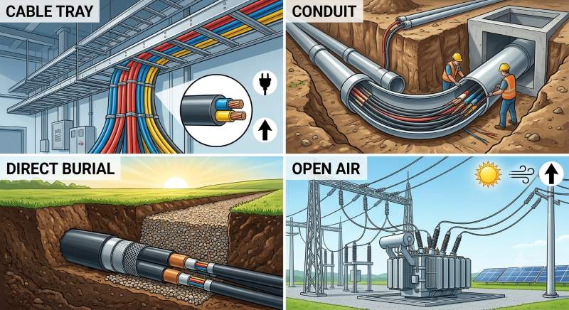
In this guide, I'll walk you through how the four main installation methods — open air, cable tray, conduit, and direct burial — affect ampacity for the same low-voltage power cable. You'll see the numbers, understand why they differ, and learn how to pick the right method for your project.
Why Installation Method Changes Ampacity
At its core, cable ampacity is a heat balance problem. A current-carrying conductor generates heat (I²R loss). That heat has to escape through the insulation, sheath, and whatever surrounds the cable — air, metal tray, plastic conduit, or soil. The better the heat path, the more current the cable can carry before hitting its maximum conductor temperature (usually 90°C for XLPE, 70°C for PVC).
So the question isn't really "how much current can this cable carry?" — it's "how fast can this installation method get the heat away?"
Reference standard: IEC 60364-5-52 (BS 7671) defines standard installation methods (A through G) with corresponding ampacity tables. NEC 310.15 does the same for North America with its own correction factors. The principles are the same — the numbers just come from different tables.
The Four Installation Methods — How Each Dissipates Heat
1. Open Air (Free Air / Ladder Tray, Spaced)
Open air, with adequate cable spacing (≥1× cable diameter), provides the best natural cooling — air circulates freely and no enclosure traps heat. This is your reference case, the baseline against which everything else is derated. Note that this assumes shaded or night-time operation; direct sunlight on dark cable sheaths adds heat and requires a solar temperature correction. Typical examples: aerial installations, cables on ladder trays with proper spacing, or long vertical runs in ventilated shafts.
2. Cable Tray (Perforated, Cables Touching)
A perforated cable tray offers decent airflow through the slots, but once cables are laid side by side — touching — they trap heat between them. The centre cables in a bunch run hotter than the outer ones. Tray fill ratio and cable spacing matter enormously here. This is one of the most common installation methods in industrial plants and commercial buildings.
3. Conduit / Duct (Surface or Embedded)
Conduit is a thermal bottleneck. In surface-mounted conduit, the air inside the pipe heats up and has limited convection. In buried ductbanks, the surrounding soil adds another layer of resistance. Long conduit runs with multiple bends get even worse because the air circulation is practically zero.
4. Direct Burial
Direct burial ampacity is dominated by soil thermal resistivity (ρ). Wet clay at ρ = 0.7 K·m/W dissipates heat surprisingly well — almost as good as open air. Dry sand or rocky backfill at ρ = 2.5 or higher can cut ampacity in half. Burial depth and spacing between circuits also play major roles. Soil moisture content is the variable nobody controls but everyone depends on.
Ampacity Comparison Table — Same Cable, 4 Methods
To make this concrete, let's take a single cable type and see how its ampacity shifts across installation methods. I've picked a common industrial workhorse: 4-core 120mm² Cu/XLPE/SWA/PVC, 0.6/1kV, 90°C conductor rating.
| Installation Method | Reference (IEC 60364) | Ampacity (A) | vs. Open Air | Key Limiting Factor |
|---|
| Open air (spaced on ladder, ≥1× OD) | Method E | 278 A | — (baseline) | Conductor temperature only |
| Perforated tray, cables touching | Method E + grouping factor | 228 A | –18% | Mutual heating reduces effective rating |
| Clipped direct to wall surface | Method C | 215 A | –23% | Wall restricts rear heat dissipation |
| Conduit on wall (surface) | Method B | 192 A | –31% | Stagnant air inside conduit |
| Conduit buried 1 m deep | Method D | 185 A | –33% | Conduit + soil thermal resistance |
| Direct burial, ρ = 1.0 K·m/W | Method D | 180 A | –35% | Soil thermal resistivity |
| Direct burial, ρ = 2.5 K·m/W | Method D | 140 A | –50% | Dry / poor soil |
Heads-up: The numbers above come from BS 7671:2018 Table 4E4B (equivalent to IEC 60364-5-52 Table B.52.5), referenced at 30°C ambient air / 20°C ground temperature, 90°C conductor rating. If you're working to the latest NEC, use NEC Table 310.16 and apply the correction factors from 310.15(B)(1) and adjustment factors from 310.15(C)(1). The relative pattern is the same — the absolute values differ by code and edition.
Notice that the worst case — dry-soil direct burial at 140 A — is barely half the open-air rating. That's not a small difference. It means a 120 mm² cable buried in poor soil may need to be upsized to 240 mm² to do the same job.
Decision Matrix — Pick the Right Installation Method
Every installation method has trade-offs. Here's how I think about them on real projects:
🌬️Open Air / Ladder Tray
Best for: Industrial plants, substations, power houses
✅ Highest ampacity per mm²
✅ Easy inspection and maintenance
❌ Exposed to physical damage
❌ Not suitable for outdoor burial
Ampacity: ★★★★★
📦Perforated Cable Tray
Best for: Commercial buildings, industrial MEP, data centres
✅ Good ampacity with proper spacing
✅ Flexible for future additions
❌ Needs careful fill-ratio planning
❌ Mutual heating if cables touch
Ampacity: ★★★★☆
🔌Conduit (Surface)
Best for: Building services, exposed runs, mechanical rooms
✅ Full mechanical protection
✅ Easy to replace / pull new cables
❌ Poor heat dissipation
❌ Ampacity derates with length
Ampacity: ★★★☆☆
🌍Direct Burial
Best for: Underground distribution, solar farms, street lighting
✅ Invisible, space-efficient
✅ Lowest installation cost (no duct)
❌ Worst ampacity in dry soil
❌ Very hard to repair
Ampacity: ★★☆☆☆
Practical Tips for Maximising Ampacity
Over the years, I've picked up a few habits that save a lot of headache when routing cables:
- Space your cables on trays. Even a gap equal to one cable diameter (1× OD) reduces mutual heating significantly. Two diameters is even better.
- Know your soil before you dig. If you're designing a direct-burial system, get a soil thermal resistivity test (per IEEE 442 or ASTM D5334). Don't guess — the difference between ρ = 1.0 and ρ = 2.5 is a 40 A swing on a 120 mm² cable.
- Use thermal backfill. If your soil is poor, replace the first 150 mm around the cable with engineered bedding (sand-cement mix or fluidised thermal backfill). It's cheap insurance.
- Avoid long conduit runs for heavily loaded cables. Every 90° bend and every metre of enclosed length reduces internal air movement. For circuits loaded above 70% of the conduit-rated ampacity, keep runs short or use a larger conduit.
- Group circuits thoughtfully. Running a power cable next to a control cable is fine. Running five fully loaded power cables touching each other — you're paying the grouping derating penalty. Spread them across separate trays or add spacing.
FAQ — Real Questions from the Field
Does cable ampacity in open air change if the cable is exposed to direct sunlight?
Yes, and it's often overlooked. Solar radiation heats the cable surface, especially dark-coloured LSZH or PVC sheaths. In outdoor above-ground installations, you should add a solar heating correction — typically 10–20°C to the ambient temperature, depending on your location. This is separate from the I²R heating. For desert or high-altitude projects, I've seen installations where solar gain added 6–8°C to the effective ambient, forcing a cable upsizing.
Can I use open-air ampacity ratings if my cable tray is covered by a solid lid or other cables on top?
Not without derating. A solid lid traps heat and blocks convection — your effective installation method shifts from "perforated tray" toward "enclosed channel." Some standards treat lidded cable trays as enclosed trunking and apply a significantly lower ampacity. If part of the tray is covered and part isn't, the whole run should be rated for the worst segment. A good rule of thumb: lidded tray ≈ 10–15% less than open perforated tray.
How does installation method affect ampacity differently for single-core vs. multi-core cables?
This is where it gets interesting. For multi-core cables, all phase conductors are inside one sheath — the heat is concentrated in one spot, so the installation method has a big impact. For single-core cables in trefoil or flat formation, the heat is spread across three separate cables, but mutual heating between phases is more complex. In open air, single-core cables in trefoil can sometimes carry more than a multi-core equivalent because each core has its own cooling surface. But in a conduit, single-core cables trapped in separate conduits per phase can suffer from circulating current losses in the sheath, which actually reduces ampacity. It's not always intuitive.
What about cables installed on a wall using cable cleats — is that the same as "clipped direct"?
Close, but not quite. "Clipped direct" (Method C in IEC 60364-5-52) assumes the cable surface is in contact with the wall, which reduces rear-side heat dissipation. If you use stand-off cleats that keep the cable 10–20 mm off the wall, you get better airflow and the ampacity sits somewhere between Method C and Method E (open air). Saddle cleats that hold the cable tight against the wall are true Method C. I'd factor a 5–8% improvement for stand-off cleats if airflow is decent.
Do harmonic currents from VFDs affect ampacity differently by installation method?
They do, and it's a specific concern for conduit runs. Harmonic currents increase RMS heating (skin and proximity effects) beyond the fundamental 50/60 Hz value. For VFD-fed cables in steel conduit, the eddy-current losses in the steel add to the thermal load. The combination of poor heat dissipation in conduit + extra harmonic heating can push the cable dangerously close to its 90°C limit. For VFD installations, I generally recommend: (1) open tray or unenclosed runs when possible, (2) symmetrical trefoil formation to cancel flux, and (3) de-rating the conduit ampacity by an additional 10% if the harmonic content exceeds 25%.
Quick Reference — Ampacity Check Before You Install
Before you lock in a cable size, run through this checklist:
- Have I confirmed the installation method that will actually be used on site — not just what's on the drawing?
- Have I applied the correct ambient temperature correction (air or soil) for the location?
- For grouped circuits: have I applied the grouping derating factor?
- For direct burial: do I have the soil thermal resistivity value, or am I guessing?
- Are there any derating interactions — e.g., grouping + high ambient + solar heating — that compound?
- Does the selected cable size still meet the voltage drop limit (usually 3–5%) after derating?
My rule of thumb: If your installation method involves any enclosure — conduit, covered tray, direct burial — assume at least a 20–30% ampacity reduction from the open-air rating. Size your cable accordingly, or step up one cross-section. A 35% ampacity cushion is cheap insurance compared to a cable replacement.
Quick Reference Table — Derating Factors by Installation
For a quick estimate during early design, here are approximate combined derating factors (relative to open air on ladder tray):
| Installation Detail | Typical Derating Factor | When to Use |
|---|
| Open air, cables spaced 1× OD | 1.00 | Reference baseline |
| Perforated tray, touching | 0.82 | Standard industrial tray installation |
| Perforated tray, spaced 1× OD | 0.90 | Well-planned tray layout |
| Solid tray (non-perforated) | 0.75 | Less common — avoid if possible |
| Conduit in air (single circuit) | 0.69 | Typical surface conduit run |
| Conduit buried (ρ = 1.0) | 0.67 | Underground ductbank, normal soil |
| Direct burial (ρ = 1.0) | 0.65 | Normal soil, 1 m depth |
| Direct burial (ρ = 2.5) | 0.50 | Dry sand, poor thermal soil |
Use these as a starting point only — always apply the official correction factors from the standard your project is governed by (IEC 60364, NEC, BS 7671, etc.) for final design.
If you're sizing cables for an upcoming project and want an ampacity check — or just need a second look at your installation routing — drop us a line at sale@sorivocable.com. Sorivo's engineers work with IEC, BS, NEC, and UL standards daily. We can help you pick the right cable and the right installation method, free of charge.
Reviewed by Luo Qiang — Senior Cable Application Engineer, Sorivo
15+ years in industrial and renewable energy cable specification. Member of IEC TC 20 (Power Cables). Previously contributed to cable selection for 500MW+ solar PV and BESS projects across Asia, Europe, and the Middle East.