Professional cable manufacturer

Professional cable manufacturer
📅 Published: 2026-06-12 | 📁 Category: Cable Installation Guide | ⏱ 14 min read
When multiple armoured cables share a trench, the spacing between them — the cable burial spread — directly determines two things: the current-carrying capacity of each circuit, and the cost of excavation. Pack them too tight and mutual heating derates the cables, forcing you to oversize conductors. Spread them too far and the trench width becomes expensive to excavate and reinstate, especially in urban or highway environments.
The challenge is that neither BS 7671 nor IEC 60364-5-52 prescribes a single "correct" spacing. Instead, they provide grouping correction factors for different spacing distances, leaving the engineer to balance thermal performance against installation cost. A 2020 industry survey by the IET found that over 30% of electrical contractors routinely omit spacing derating from their cable sizing calculations — leading to cables operating above their rated temperature in service.
This guide provides a practical reference for specifying cable burial spread: the correction factors from IEC 60364-5-52 and BS 7671, depth requirements, installation methods, soil thermal resistivity impacts, and worked examples for common trench configurations. Whether you are designing a residential street lighting feeder or a utility-scale industrial power trench, understanding burial spread is essential for safe and cost-effective cable installation.
Minimum burial depth is the starting point for any direct buried cable installation. The required depth depends on the voltage rating, the mechanical protection provided, and the risk of disturbance from surface activities.
| Installation Condition | Minimum Depth (mm) | Reference |
|---|---|---|
| General ground (LV, SWA armoured) | 600 | BS 7671 Reg 522.8.10 / Industry practice |
| Under hard standing (paving, concrete, tarmac) | 300 | BS 7671 Reg 522.8.10 / Industry practice |
| High-voltage cables (11 kV / 33 kV) | 750–1000 | DNO requirements / ENA TS 41-24 |
| Under roads (with mechanical protection) | 1000 | New Roads and Street Works Act / HAUC |
| In agricultural land (plough depth risk) | 900–1000 | EA Technical Advice Note |
| IEC standard burial depth (reference) | 700 (LV) / 800 (MV) | IEC 60364-5-52 |
When cables are buried deeper than the standard reference depth, the ampacity must be derated due to higher soil thermal resistivity at depth. IEC 60364-5-52 provides depth correction factors:
| Burial Depth (mm) | Correction Factor (LV, 0.6/1kV) |
|---|---|
| 500 | 1.04 |
| 700 (reference) | 1.00 |
| 800 | 0.98 |
| 1000 | 0.94 |
| 1200 | 0.91 |
| 1500 | 0.87 |
Factors are approximate and vary with cable type and soil conditions. Always verify with manufacturer data or IEC 60287 calculation for critical installations.
When multiple circuits share a trench, mutual heating reduces each cable's ability to dissipate heat. The magnitude of this reduction depends on the number of circuits and the centre-line spacing between them. IEC 60364-5-52 Annex B and BS 7671 Table 4C2 provide the standardised grouping factors for direct buried multi-core cables.
| Number of Circuits | Touching (nil clearance) | 1× Cable Diameter | 0.125 m | 0.25 m | 0.5 m |
|---|---|---|---|---|---|
| 2 | 0.75 | 0.80 | 0.85 | 0.90 | 0.90 |
| 3 | 0.65 | 0.70 | 0.75 | 0.80 | 0.85 |
| 4 | 0.60 | 0.60 | 0.70 | 0.75 | 0.80 |
| 5 | 0.55 | 0.55 | 0.65 | 0.70 | 0.80 |
| 6 | 0.50 | 0.55 | 0.60 | 0.70 | 0.80 |
| 7 | 0.45 | 0.51 | 0.59 | 0.67 | 0.76 |
| 8 | 0.43 | 0.48 | 0.57 | 0.65 | 0.75 |
Source: BS 7671 Table 4C2 (equivalent to IEC 60364-5-52 Table B.52.19). Applies to homogeneous groups of equally loaded multi-core cables, buried direct in horizontal or vertical arrangement.
A 16 mm² 4-core SWA cable rated 96 A clipped direct may have a base buried rating closer to 80 A (depending on soil conditions). If three such circuits share a trench with cables touching:
That is a 12 A difference per circuit — or 23% more capacity — simply by maintaining 250 mm spacing instead of laying cables touching. The spacing costs nothing in material but can save a full conductor size upgrade.
| Factor | Standard Market Cable | SORIVO Armoured Cable |
|---|---|---|
| Conductor | Plain copper (may not meet BS EN 60228) | Class 2 stranded copper, BS EN 60228 certified |
| Insulation | PVC or unknown-grade XLPE | XLPE Type GP8 to BS 7655 — 90°C rated |
| Armour | Variable wire count and gauge | Galvanised SWA to BS standards, consistent wire diameter |
| Outer sheath | PVC (unverified UV/abrasion resistance) | PVC Type 9 or LSZH LTS1, carbon-black loaded |
| Traceability | May lack metre marking | Metre-marked, batch-traceable, BASEC-certified |
| Warranty | 5–15 years | 25 years (direct burial design life) |
Grouping factors account for mutual heating between cables. But the soil thermal resistivity (measured in K·m/W) determines how effectively the combined heat dissipates into the surrounding ground. This varies dramatically with soil type, moisture content, and compaction.
| Soil Type | Thermal Resistivity (K·m/W) | Typical Condition |
|---|---|---|
| Waterlogged clay / saturated sand | 0.5–0.8 | Excellent heat dissipation |
| Moist clay / loam | 1.0–1.5 | Good — typical UK conditions |
| Damp sand / gravel | 1.5–2.0 | Moderate |
| Dry sand / chalk | 2.0–2.5 | Poor — requires significant derating |
| Dry desert / limestone | 2.5–3.0 | Very poor — maximum derating |
IEC 60364-5-52 Table B.52.16 provides correction factors for soils with thermal resistivity different from the reference value of 2.5 K·m/W:
| Soil Thermal Resistivity (K·m/W) | Correction Factor (Multi-core, Direct Buried) |
|---|---|
| 0.7 | 1.18 |
| 1.0 | 1.13 |
| 1.5 | 1.05 |
| 2.0 | 1.02 |
| 2.5 (reference) | 1.00 |
| 3.0 | 0.96 |
| 4.0 | 0.89 |
For a real installation, all three factors must be applied sequentially:
The following section maps standard trench configurations to their equivalent grouping factors, helping designers choose the most cost-effective layout.
| Trench Configuration | Typical Trench Width | Grouping Factor (4 circuits) | Comment |
|---|---|---|---|
| Cables laid touching in single layer | Narrow (just wider than cable bundle) | 0.60 | Lowest cost trench, highest derating |
| Circuits spaced at 125 mm centres | ~600–800 mm (4 circuits) | 0.70 | Good balance of trench width and derating |
| Circuits spaced at 250 mm centres | ~1000–1200 mm (4 circuits) | 0.75 | Wider trench, minimal derating penalty |
| Two layers (cables in spaced formation) | ~500 mm | 0.65–0.70 | Saves trench width but adds depth |
| Separate trenches, >3 m apart | Individual narrow trenches | 1.00 (no grouping effect) | Most expensive — only used for high-capacity circuits |
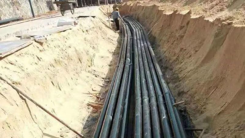
TYPICAL TRENCH CROSS-SECTION — 4 CIRCUITS AT 125 mm SPACING
   ╔═══════════════════════════════════════════════╗
   ║  COMPACTED BACKFILL / SURFACE REINSTATEMENT    ║
   ╚═══════════════════════════════════════════════╝
   ——————————————— WARNING TAPE @ 150 mm ———————————————
   ╔═══════════════════════════════════════════════╗
   ║                BACKFILL MATERIAL                ║
   ║    ┌──────┐   ┌──────┐   ┌──────┐   ┌──────┐   ║
   ║    │SWA 1 │   │SWA 2 │   │SWA 3 │   │SWA 4 │   ║
   ║    └──────┘   └──────┘   └──────┘   └──────┘   ║
   ║    <—125—><—125—><—125—>                    ║
   ╠═══════════════════════════════════════════════╣
   ║             SAND BEDDING (100 mm)              ║
   ╚═══════════════════════════════════════════════╝
Minimum cover: 600 mm (general) / 300 mm (under hard standing) | Sand bedding: 100 mm below and 100 mm above cable
| Number of Circuits | Touching (min width) | 125 mm spacing | 250 mm spacing |
|---|---|---|---|
| 2 | ~100 mm | ~375 mm | ~625 mm |
| 3 | ~150 mm | ~500 mm | ~850 mm |
| 4 | ~200 mm | ~625 mm | ~1075 mm |
| 5 | ~250 mm | ~750 mm | ~1300 mm |
| 6 | ~300 mm | ~875 mm | ~1525 mm |
Assumes cable OD ≈ 20 mm (typical 16 mm² 4-core SWA). Widths are centre-line spacings plus half-OD overhang on each side.
Getting burial spread wrong does not always cause an immediate failure. The damage is cumulative — accelerated thermal ageing that shortens cable life by years.
XLPE insulation rated for 90°C continuous operation has a design life of approximately 25 years at rated temperature. According to the Arrhenius ageing model, every 10°C increase above rated temperature reduces insulation life by approximately 50%. If grouping derating is ignored and the cable operates at 100°C conductor temperature instead of 90°C, the expected life drops from 25 years to roughly 12–13 years.
| Scenario | Conductor Temperature | Approx. XLPE Insulation Life | Replacement Cost (per km trench) |
|---|---|---|---|
| Correctly derated (spaced at 250 mm) | ~85–90°C | 25 years + | £0 (no replacement needed) |
| Spacing ignored (touching, 6 circuits) | ~100–105°C | ~12–15 years | £8,000–12,000 per km |
| Spacing ignored + dry soil (3.0 K·m/W) | ~110–115°C | ~6–8 years | £15,000–20,000 per km |
A building control or DNO inspection that finds cables operating above their rated temperature due to unaccounted grouping can result in:
Before accepting a supplier's current rating table for direct buried cables, use these practical checks to ensure the published values apply to your installation conditions.
For a complete walkthrough of cable verification, see our guide: How to Verify Cable Certification (methodology applies to BS standards as well).
Correct burial spread design follows three steps, applied in order:
For the majority of low-voltage direct-buried installations, a 125–250 mm spacing between circuits with a 600 mm minimum cover depth and properly compacted sand bedding provides a reliable, code-compliant configuration that maximises ampacity while keeping trench width manageable.
At SORIVO, all armoured cables are manufactured to BS 5467 or BS 6724 with full BASEC certification, metre-marked traceability, and published derating data to support accurate trench design.
Further reading:
We supply BS 5467 and BS 6724 cables with full BASEC certification, batch traceability, and published derating data. Our technical team can provide cable sizing calculations including grouping and soil resistivity factors for your specific trench configuration.
Request a Cable Sizing Proposal📧 sale@sorivocable.com | 📞 +86 192 8290 5529
No — cables installed in buried ducts (installation method D1) have different grouping factors from cables buried direct in the ground (method D2). Ducts trap heat and reduce the cooling effect of the surrounding soil. IEC 60364-5-52 Table B.52.18 provides the grouping factors for cables in buried ducts, which are generally 5–10% lower than the equivalent direct-burial factors. If your cable runs in duct for any portion of the route, use the duct grouping factors for the entire length or calculate the mixed-route rating separately.
The grouping factors in Table 4C2 assume homogeneous groups — cables of the same size, type, and loading. If the trench mixes cable sizes (e.g., a 95 mm² feeder alongside a 6 mm² lighting circuit), the larger cable generates more heat, and the smaller cable is more affected by mutual heating. In mixed-size installations, apply the grouping factor to the largest cable and double-check the smaller cable's temperature rise separately. A conservative approach is to use the factor for one additional circuit (e.g., if you have 4 cables, use the factor for 5 circuits).
For thermal independence between direct-buried circuits, a centre-line spacing of approximately 3 metres is generally accepted as sufficient to eliminate mutual heating effects (grouping factor = 1.0). At this spacing, each cable experiences the ground at ambient temperature, unaffected by adjacent circuits. However, 3 m spacing is rarely practical for multi-circuit trenches. In practice, 500 mm spacing gives a factor of 0.80 for 4 circuits — a reasonable compromise that avoids significant derating while keeping trench width under 1.5 metres.
Yes — significantly. Standard sand bedding has a thermal resistivity of approximately 2.0–2.5 K·m/W when dry, but as low as 0.5–0.8 K·m/W when moist. Thermal backfill (engineered sand-cement mixes or crushed rock with controlled grading) can achieve resistivities as low as 0.5–0.8 K·m/W, dramatically improving heat dissipation. If the trench uses thermal backfill, the soil resistivity correction factor from Table B.52.16 may allow a 15–25% uprating compared to standard sand backfill. Always specify the backfill type in the cable installation specification.
At corners and termination points, cables inevitably converge. The grouping factors in Table 4C2 assume a consistent spacing along the entire cable route. If cables run touching for short sections (less than 1–2 metres at corners or in cable pits), the thermal impact is usually negligible because heat conducts axially along the cable. However, if the touching section exceeds 5 metres, reduce the grouping benefit proportionally. The conservative approach: use the closest-spacing factor that applies for more than 10% of the cable route. For long parallel runs with short convergence sections, the standard spacing factor governs.