Professional cable manufacturer

Professional cable manufacturer
Home » Products » Solar Cable » 4mm² Solar Extension Cable with MC4 Connectors
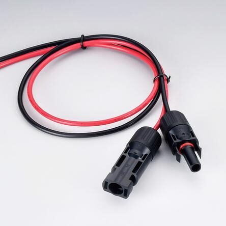
A factory pre-terminated PV extension assembly — H1Z2Z2-K 4mm² tinned-copper cable crimped to an IEC 62852 MC4-compatible male/female pair, cut to your length. The DC string is plugged together on site, not crimped.
Everything a solar engineer checks first — before diving into the full datasheet below.
This is not cable sold by the metre. It is a finished DC assembly: H1Z2Z2-K 4mm² photovoltaic cable cut to length, terminated at the factory with an MC4-compatible male and female pair, continuity checked and pull-tested before it is packed. What arrives on site is a part that plugs into the next one. Loose contact pins, wrong crimp dies, half-inserted grommets and mismatched polarity are the most common causes of a hot joint on a PV array, and every one of them is an on-site termination problem.
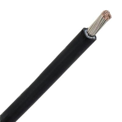
The cable core is H1Z2Z2-K to EN 50618 / IEC 62930 — single-core, Class 5 flexible stranded tinned copper, electron-beam cross-linked XLPO insulation and sheath, halogen-free and low smoke. In 4mm² it carries 55 A in free air at 60°C ambient and its maximum DC resistance is 5.09 Ω/km at 20°C, a loop voltage drop of about 10.18 V/A/km across the complete circuit.
The connectors are rated to IEC 62852, the standard for connectors used in photovoltaic systems. The pair is rated 30 A continuous (50 A peak) at up to 1500V DC, uses tin-plated copper contacts with ≤ 0.5 mΩ contact resistance, and seals to IP68 when mated. The bayonet-lock coupling is tool-free to close and releases with a standard MC4 release tool, and the housing is UL94 V-0 rated PPO/PPE.
The assembly rating is the lower of the two: 30 A continuous, set by the connector. That is the honest number for a 4mm² pre-terminated assembly and it is the one to design a string against. Moving up to 6 mm² does not raise that figure — the same 30 A connector pair caps the 6 mm² assembly too, so the larger cable buys lower resistance and voltage drop (3.39 against 5.09 Ω/km), not more current. Assembly temperature limits are the tighter of the cable and connector figures — the ambient range is −40°C to +90°C for the cable and −40°C to +85°C at the connector.
More about the manufacturer: About SORIVO →
Male and female MC4-compatible connectors are crimped and assembled in the factory, then pull-tested to ≥ 50 N and continuity-checked — no field crimping tools, no crimp-quality variance between crews.
The connector pair is built to the IEC 62852 standard for PV connectors, rated 30 A continuous and 50 A peak at up to 1500V DC, with a 6 kV AC / 1 minute proof test. The safety class of an MC4-type connector is voltage-dependent — confirm the class for your system voltage on the certificate.
The mated pair is sealed to IP68 — verified at 1 m depth for 1 hour. A dual-injection moulded seal body around the contact core keeps moisture out of the joint through rain, wash-down and ground-mount flooding.
Both the cable and the connector pair are rated for 1500V DC systems, matching modern high-voltage string architectures with longer strings and fewer combiner boxes.
Tin-plated copper contacts keep contact resistance at ≤ 0.5 mΩ, which is where a PV joint actually loses power and generates heat. Tinned rather than bare copper keeps that surface stable in humid and coastal air.
The snap-in bayonet coupling closes by hand and is released with a standard MC4 release tool, so connections stay serviceable for string testing, module replacement and re-stringing without cutting cable.
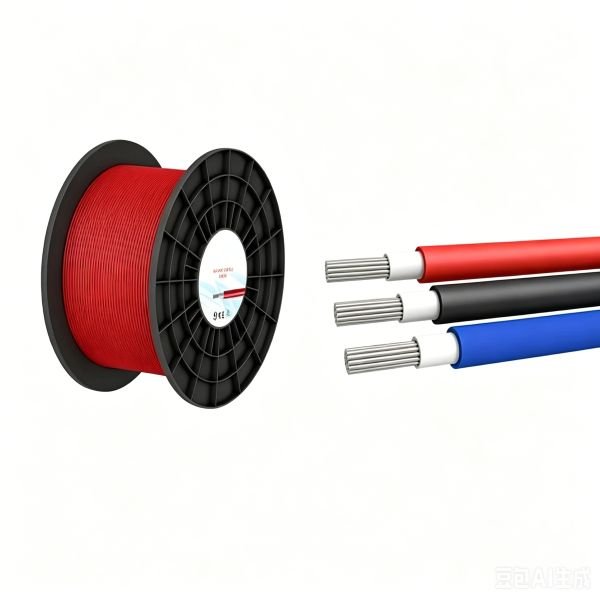
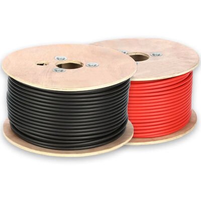
Cut to order from 0.3 m to 20 m with no minimum increment, in black for DC− and red for DC+, or as flying leads, female-to-female, male-to-male and Y-branch variants.
Class 5 stranded tinned copper conductor in the cable and tin-plated copper contacts in the connector — one corrosion-resistant metal system across the whole current path, with no bare-copper transition.
Any DC segment that is measured, cut and terminated on site is a segment that can be shipped already made.
The short link between adjacent modules in a row, where 4mm² is the standard size and the connector quality decides the joint temperature.
Bridging the gap between the end of a module row and the next, in the exact length the layout needs instead of a coiled standard jumper.
The final run from the last string connector into the inverter or DC combiner, terminated with the connector the inverter input expects.
String tails into the combiner enclosure, where an IP68 factory joint removes the need to re-crimp inside a confined box.
Re-stringing and module replacement on existing rooftops, where assemblies can be made up in advance and fitted in a single visit.
Volume sites where thousands of identical, pre-measured jumpers are the difference between a scheduled and a slipping commissioning date.
Pontoons, tracker rows and open ground where the IP68 mated seal and the tinned contact surfaces face permanent humidity.
Small systems built from kits, where a ready-made assembly means the installer does not need to own a crimping tool at all.
The complete parameter set — the same data our engineers quote from.
| Cross-section mm² | Conductor dia. max. mm | Overall diameter min. – max. mm | Weight approx. kg/km | Min. bending radius fixed, mm | Max. DC resistance at 20°C, Ω/km | Current in free air at 60°C, A | Short-circuit current 1 s, kA |
|---|---|---|---|---|---|---|---|
| 1.5 | 1.6 | 4.4 – 5.0 | 35 | 15 | 13.7 | 30 | 0.21 |
| 2.5 | 1.9 | 4.8 – 5.4 | 46 | 17 | 8.21 | 41 | 0.36 |
| 4 | 2.4 | 5.3 – 5.9 | 61 | 18 | 5.09 | 55 | 0.57 |
| 6 | 2.9 | 5.8 – 6.4 | 80 | 20 | 3.39 | 70 | 0.86 |
| 10 | 4.0 | 7.0 – 7.6 | 122 | 23 | 1.95 | 98 | 1.43 |
| 16 | 5.6 | 9.0 – 9.8 | 200 | 30 | 1.24 | 132 | 2.29 |
| 25 | 6.4 | 10.3 – 11.2 | 290 | 34 | 0.795 | 176 | 3.58 |
| 35 | 7.5 | 11.7 – 12.5 | 400 | 50 | 0.565 | 218 | 5.01 |
The 4 mm² row is highlighted — it is the size these assemblies are built on. The same cable core is produced from 1.5 mm² to 35 mm², with larger sizes to order; pre-terminated assemblies are offered in 4 mm² as standard and 6 mm² on request. Dimensions and weights are the published nominal figures for EN 50618 single-core cable and are subject to manufacturing tolerance; the values on the order confirmation take precedence. The current column is one cable in free air at 60°C ambient and must be derated for higher ambient temperature, grouping and enclosure — EN 50618 Table A4 factors are 0.92 at 70°C, 0.84 at 80°C and 0.75 at 90°C. Maximum DC resistance values are the IEC 60228 Class 5 tinned-copper limits.
| Cable — General | |
| Product Name | 4mm² Solar Extension Cable with MC4 Connectors (pre-terminated assembly) |
| Cable Type | H1Z2Z2-K single-core photovoltaic cable, 1 × 4 mm²; also available on PV1-F (TÜV 2PfG 1169) cable to order |
| Primary Standard | EN 50618:2014 — cables for photovoltaic systems; IEC 62930 |
| Further Standards | EN 60228 / IEC 60228 (conductor); EN 50565-1 (bending radius); EN 50575 (CPR, class stated on the Declaration of Performance) |
| Rated Voltage AC | U0/U 1.0/1.0 kV AC, maximum permissible operating voltage 1.2/1.2 kV |
| Rated Voltage DC | U0/U 1.5/1.5 kV DC, maximum permissible operating voltage 1.8/1.8 kV — for 1500V DC PV strings |
| Test Voltage (Cable) | 6.5 kV AC or 15 kV DC (alternative tests), 5 minutes |
| Cable — Conductor | |
| Conductor Material | Electrolytic tinned copper — corrosion-resistant strand surface |
| Conductor Type | Class 5 flexible stranded conductor, per EN 60228 / IEC 60228 |
| Max. DC Resistance | 4 mm²: 5.09 Ω/km at 20°C (other sizes in Table 1) |
| Conductor Diameter | 4 mm²: 2.4 mm maximum |
| Cable — Insulation & Sheath | |
| Insulation Material | XLPO (cross-linked polyolefin), electron-beam cross-linked, halogen-free |
| Sheath / Jacket | XLPO (cross-linked polyolefin), LSZH, UV and ozone resistant |
| Core / Sheath Colour | Black (standard, DC−) and red (DC+); other colours on request |
| Halogen-Free | IEC 60754-1; no corrosivity per IEC 60754-2 |
| Smoke Density | IEC 61034-1 / -2 — light transmittance > 70% |
| Sheath Marking | SORIVO H1Z2Z2-K 1 × <size> mm² 1.0/1.0 kV AC 1.5 kV DC EN 50618 IEC 62930 <year> — or per customer requirement |
| Cable — Electrical & Thermal | |
| Current Carrying Capacity | 4 mm²: 55 A free in air, 52 A on a surface, 44 A for two loaded cables touching, all at 60°C ambient (other sizes in Table 1) |
| Voltage Drop (4 mm²) | ≈ 10.18 V/A/km for the complete circuit loop at 20°C conductor temperature, calculated from the maximum conductor resistance |
| Insulation Resistance | ≥ 800 MΩ·km at 20°C — in-house routine test value |
| Ambient Temperature | −40°C to +90°C for fixed installation; −25°C to +60°C during handling and installation |
| Max. Conductor Temperature | +90°C continuous; +120°C for up to 20 000 h |
| Max. Short-Circuit Temperature | +250°C for a maximum of 5 seconds |
| Minimum Bending Radius | 3 × overall diameter up to 12 mm OD, 4 × overall diameter above 12 mm OD per EN 50565-1; published value for 4 mm² is 18 mm |
| UV Resistance | EN 50618 Annex E — 720 h / 360 cycles to EN 50289-4-17 method A |
| Ozone Resistance | Per EN 50396, test type B |
| Water Resistance | AD7 immersion per EN 50618; higher AD8 rating agreed per order and supported by the test record for the construction supplied |
| Flame Performance | IEC / EN 60332-1-2, single cable vertical flame propagation |
| Design Life | Minimum 25 years per EN 50618; 30 years at 90°C continuous conductor temperature on the Arrhenius basis |
| Connector Pair — MC4-Compatible | |
| Product Model | MC4-30A-IP68 — male + female bayonet-locking pair, pre-assembled |
| Connector Standard | IEC 62852; CE |
| Compatibility | Ø 4 mm MC4-type contact system — mates MC4 / Standard4 / PV4-style interfaces. Use one brand across a mated pair: mixed-brand pairs sit outside the IEC 62852 approval and are a known cause of DC arcing. MC4 is a registered trademark of Stäubli. |
| Rated Current | 30 A continuous, 50 A peak |
| Rated Voltage DC | 1000V – 1500V DC |
| Test Voltage (Connector) | 6 kV AC, 50 Hz, 1 minute |
| Contact Resistance | ≤ 0.5 mΩ |
| Contact Material | Tin-plated copper contacts, 99.98% copper purity |
| Housing Material | PPO / PPE, UL94 V-0 flammability rated |
| Ingress Protection | IP68 mated — verified at 1 m depth for 1 hour |
| Safety Class | Class II at DC 1100 V; Class 0 at DC 1500 V — voltage-dependent, see note below |
| Insertion / Pull-Out Force | Insertion ≤ 50 N; pull-out ≥ 50 N |
| Locking System | Bayonet-lock coupling, tool-free to close, released with a standard MC4 release tool |
| Connector Temperature | −40°C to +85°C |
| Accepted Cross-Section | 4 mm² and 6 mm² (AWG 10 – 12) |
| Assembly, Options & Logistics | |
| Assembly Current Rating | 30 A continuous — set by the connector, which is the lower of the cable (55 A) and connector (30 A) ratings |
| Available Lengths | 0.3 m to 20 m cut to any increment; standard 0.3 / 0.5 / 1 / 2 / 3 / 5 / 10 m; longer assemblies up to 50 m on request |
| End Configurations | Male–female (standard), female–female, male–male, connector-to-flying-lead, Y-branch, T-branch and fused variants |
| Routine Testing | Continuity and polarity verification plus connector pull-out test on every assembly; batch records retained |
| Packaging | Poly bag + inner box, bulk pack or custom packing per request |
| MOQ | 100 pcs; sample orders negotiable |
| Lead Time | 5–10 working days; stocked lengths may be available in 2–3 days |
Final selection should be based on string current, system voltage, run length, short-circuit conditions, installation method and applicable local requirements. The assembly rating is limited by the connector, not by the cable: the MC4-compatible pair is rated 30 A continuous with a 50 A peak, so moving from 4 mm² to 6 mm² lowers resistance and voltage drop but does not raise the assembly's continuous rating. If a string needs more than 30 A continuous, tell us and we will quote the connector system that suits it. On safety class: for MC4-type PV connectors the published IEC practice is Class II at DC 1100 V and Class 0 at DC 1500 V — the class follows the voltage rating of the construction ordered. The class applying to your order is stated on the connector certificate, so confirm it against your system voltage before specifying a 1500V DC string. Our engineers confirm the exact construction and certification scope with your project data.
The European standard for cables in photovoltaic systems and its IEC equivalent, covering the H1Z2Z2-K cable core of this assembly. Certificate of conformity on request.
Request certificate copy →The standard for connectors used in photovoltaic systems, covering the MC4-compatible pair fitted to this assembly: rated current and voltage, contact resistance, IP68 sealing and locking. Type-test documents available on request.
Request test report →Cable to IEC 60332-1-2, IEC 60754-1 and -2 and IEC 61034 with light transmittance above 70%; connector housing rated UL94 V-0. The fire performance set required for rooftops and enclosed DC installations.
Request test report →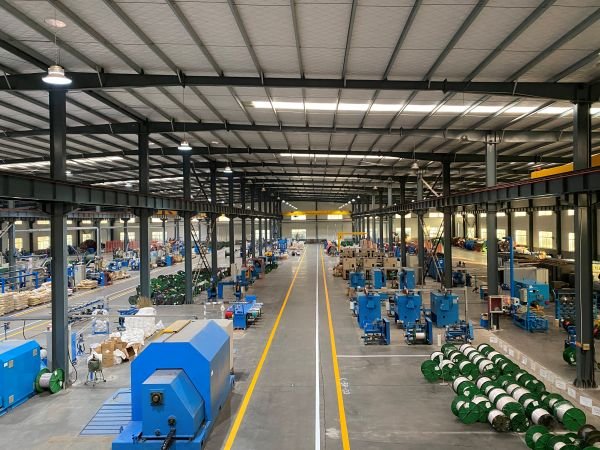
The cable is extruded and tested under our own roof, and the assembly is crimped on the same site — which is why we can test the joint rather than just the components.
Tell us the length, cross-section, end configuration, colour and quantity.
We confirm cable type, connector pairing, labelling and quotation within one working day.
Sample assemblies for fit and connector-mating checks — a few working days for stocked lengths.
Cable extrusion, crimping and 100% continuity testing. Lead time 5–10 working days.
Bagged and boxed per length, with shipping documents and after-sales support.
Tell us the length, cross-section and end configuration — we reply within one working day.
The more detail you give, the faster and more accurate our quotation. Our engineers reply within one working day.
Thanks — our engineers will reply within one working day.