Professional cable manufacturer

Professional cable manufacturer
Home » Products » Power Cable » Mining Trailing Cable with TPU Sheath 6/10kV–14/25kV
Three-core screened mining trailing cable for draglines, continuous miners, shovels and shuttle cars — the ICEA S-75-381 Type SHD-GC portable trailing construction, with a TPU sheath supplied as an order-specific jacket option.
What a mine electrical engineer checks first — before the full datasheet below.
This is a three-core medium-voltage screened portable trailing cable for mines and similar applications, of the construction that ICEA S-75-381 / NEMA WC 58 calls Type SHD-GC — the portable trailing section of that standard, covering 5 001–25 000 V at the 100 % insulation level. Its dimensions and tests sit in the IEC 60502-2 framework, which is where the U0/U designations on this page come from.
The two voltage systems on this page are deliberately kept apart. 6/10 kV, 8.7/15 kV and 14/25 kV are IEC/VDE U0/U values — U0 is the conductor-to-earth voltage and U the conductor-to-conductor voltage. ICEA instead works with single-number classes: 8 kV, 15 kV and 25 kV, all at the 100 % insulation level. A cable rated 6/10 kV in IEC terms sits in the ICEA 8 kV class; 14/25 kV sits at the top of the ICEA portable range, whose ceiling is 25 000 V. Never read a figure from one column against the other.
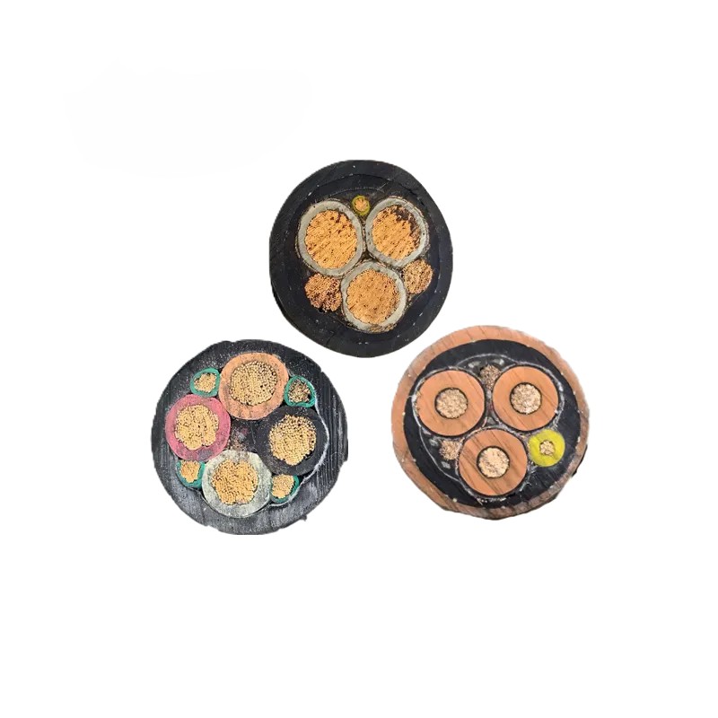
Each power core is a Class 5 flexible tinned copper conductor to IEC 60228, rope-lay stranded. Over it sits an extruded semiconductive stress-control layer, then EPR insulation, then an extruded semiconductive insulation screen — the three layers applied in one triple-extrusion and cross-linked together, which is what keeps the conductor screen and the insulation screen bonded to the wall instead of lifting at the interface under repeated flexing. Over the screen comes a semiconductive tape and a flexible copper/textile braid.
The braid is not decoration: with a screened medium-voltage cable the metallic shield must be effectively earthed at every point where the cable is cut and terminated. The two tinned copper grounding conductors run in contact with the braid so that the earth path travels with the cable; the third auxiliary core is the ground-check conductor, tinned copper insulated with high-strength yellow polypropylene, which is what allows the trailing machine's earth-continuity monitor to prove the circuit before power is applied.
The standard ICEA configuration for SHD-GC is a double-reinforced, lead-cured CPE sheath; the TPU sheath this page is named for is an order-specific option, which we state plainly rather than implying that TPU is what ICEA requires. Temperature-wise the conductor is rated +90°C continuous and the cable is specified to reel at −30°C without cracking. Power-core sizes run 3×50 mm² to 3×185 mm². The insulation wall for this voltage class is 3.4 mm at 6/10 kV, 4.5 mm at 8.7/15 kV and 6.8 mm at 14/25 kV — these are the published values for comparable SHD-GC constructions of the same voltage class, not a SORIVO-run measurement; our own drawings and type-test report govern the cable we actually ship, and we confirm them against your specification before quoting.
More about the manufacturer: About SORIVO →
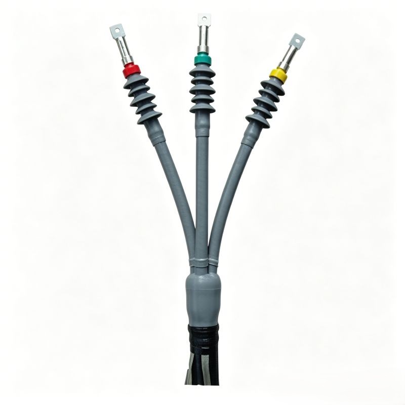
The portable trailing construction: screened 3-core, grounding conductors and one ground-check conductor. We do not also badge it MP-GC — that is the mine-feeder section of the same standard.
For this voltage class the construction is a semiconductive conductor screen, an EPR wall and a semiconductive insulation screen extruded in one pass and cross-linked together, so the interfaces stay bonded through continuous flexing.
Each power core carries a semiconductive tape plus a flexible copper/textile braid. On a screened MV trailing cable the metallic screen has to be effectively earthed wherever the cable is terminated — a precondition of safe operation, not an accessory.
The conductor runs at +90°C continuously. Under short circuit +200°C is permitted; the duration is set by the installation and must be confirmed against the project's protection settings.
Rated and flexible at −30°C: it reels without cracking or sheath splitting, which is the condition that decides whether a shift change on a cold bench damages the cable.
ICEA S-75-381 configures SHD-GC with a double-reinforced lead-cured CPE sheath. The TPU sheath on this page is an order-specific option for extra-heavy-duty abrasion, cutting and oil exposure.
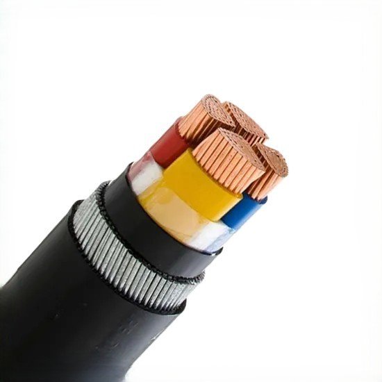
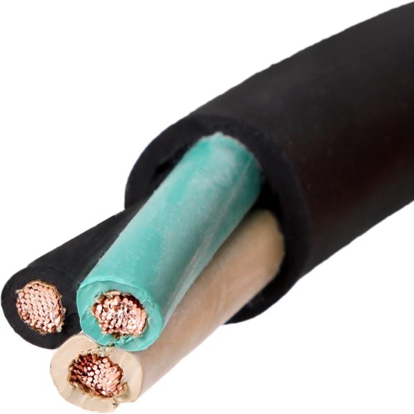
Three power cores, two tinned copper grounding conductors in contact with the braid, and one ground-check core insulated with high-strength yellow polypropylene for earth-continuity monitoring.
MSHA acceptance for mining cable is carried as an approval number printed on the sheath; comparable mining jackets also show the CSA FT1 / FT5 flame marks and SR sunlight resistance. The approvals that apply to your construction are confirmed in the offer.
Trailing, reeling and repeatedly re-routed MV power — surface and underground.
The trailing run that follows the shearer along the face, flexing with every pass and taking the floor's abrasion at the same time.
Cutter-head and gathering-arm power on a machine that never stands still, where a sheath failure stops the whole section.
Open-pit power shovels and draglines, including slag-reclaiming duty where hot, abrasive spoil is dragged across the sheath.
Dredge ladder and cutter power and rig trailing runs, where the cable works in wet, gritty conditions and is moved on every shift.
Self-propelled machines fed from a cable reel, where the cable is spooled and unspooled repeatedly and torsional load builds along the run.
MV distribution that has to be picked up and re-routed as the workings advance, instead of staying in one fixed trench.
Bench and quarry trailing runs, including gantry-crane duty, where UV, ozone and weather exposure come on top of mechanical wear.
Duty in dry, damp and water-immersed locations and on outdoor benches, provided the screen is earthed and the bend radius is respected.
The complete parameter set — the same data our engineers quote from.
| Voltage class IEC U0/U | Power cores mm² | Reference nominal insulation mm | Reference nominal sheath mm | Approx. overall dia. mm | Approx. weight kg/km | Max. DC resistance at 20°C, Ω/km | Current rating at 30°C ambient, A |
|---|---|---|---|---|---|---|---|
| 6/10 kV | 3×50 | 3.4 | 5.5 | 54.0 | 2 430 | 0.393 | 202 |
| 6/10 kV | 3×70 | 3.4 | 5.5 | 54.8 | 3 072 | 0.277 | 250 |
| 6/10 kV | 3×95 | 3.4 | 5.5 | 62.6 | 4 901 | 0.210 | 301 |
| 6/10 kV | 3×120 | 3.4 | 5.5 | 66.3 | 5 467 | 0.164 | 352 |
| 6/10 kV | 3×185 | 3.4 | 5.5 | 75.6 | 8 100 | 0.108 | 461 |
| 8.7/15 kV | 3×50 – 3×185 | 4.5 | 5.5 | per project | per project | 0.393 – 0.108 | 202 – 461 |
| 14/25 kV | 3×50 | 6.8 | 5.5 | 65.1 | 6 800 | 0.393 | 202 |
| 14/25 kV | 3×70 | 6.8 | 5.5 | 69.7 | 8 000 | 0.277 | 250 |
| 14/25 kV | 3×95 | 6.8 | 5.5 | 75.3 | 9 000 | 0.210 | 301 |
| 14/25 kV | 3×120 | 6.8 | 5.5 | 78.3 | 9 400 | 0.164 | 352 |
| 14/25 kV | 3×185 | 6.8 | 5.5 | 86.3 | 14 000 | 0.108 | 461 |
Reference construction values. The figures in Table 1 are the published data of externally manufactured SHD-GC constructions in these voltage classes — they are shown so you can see the range this product is built within, not as a SORIVO-run measurement. They do not replace our own drawings and type-test report, which are the documents that govern the cable we ship and which we confirm against your specification before quoting. The 6/10 kV 3×95 mm² row is highlighted as the mid-range example. Insulation and sheath thicknesses are the nominal values of the reference construction and are not an industry-wide minimum — comparable SHD-GC cables are published at 5.0–7.5 mm of sheath at 15 kV and 6.7–7.5 mm at 25 kV. Resistance and current columns are identical between the 6/10 kV and 14/25 kV reference builds because the conductor and the 30°C ambient basis are the same; the two builds differ in insulation thickness, overall diameter and weight, so the columns must not be read across. For the 8.7/15 kV class the published reference data covers insulation thickness and the conductor range only, so diameter and weight are quoted per project. Current ratings assume a 30°C ambient; apply the derating factor for the ambient and grouping of your installation. Dimensions are nominal and subject to manufacturing tolerance.
| General Information | |
| Product Name | Mining Trailing Cable with TPU Sheath 6/10kV–14/25kV (three-core, screened) |
| Construction Type | Type SHD-GC — the portable trailing cable construction defined in ICEA S-75-381 / NEMA WC 58, section 3. This cable is offered to that construction; it is not badged MP-GC, which is the mine-feeder section of the same standard. |
| Primary Standard | ICEA S-75-381 / NEMA WC 58 (current edition ANSI/NEMA WC 58-2017) — portable and power feeder cables for use in mines and similar applications |
| Further Standards | IEC 60502-2 (MV dimensions and tests); IEC 60228 (Class 5 conductor); ASTM B 172 (rope-lay stranded copper); IEC 60228 class 5 as an alternative conductor basis |
| Rated Voltage — IEC/VDE U0/U | 6/10 kV · 8.7/15 kV · 14/25 kV (U0 = conductor to earth, U = conductor to conductor) |
| Rated Voltage — ICEA Classes | 8 kV · 15 kV · 25 kV single-number classes at the 100 % insulation level. The ICEA portable range is capped at 25 000 V. The two systems are listed separately and are never mixed in one figure. |
| AC Test Voltage | This voltage class is tested at 17 kV AC (6/10 kV), 24 kV AC (8.7/15 kV) and 36 kV AC (14/25 kV) for 5 minutes, the levels published for comparable SHD-GC constructions. The test level applied to your order is certified on the routine test record that ships with the drum. |
| Core Configuration | 3 power cores + 2 grounding conductors + 1 ground-check conductor (3+2+1) |
| Power Core Range | 3×50 mm² to 3×185 mm² at both 6/10 kV and 14/25 kV. In the AWG/kcmil system, comparable published SHD-GC cables of this family span 4 AWG to 500 kcmil at the 8 kV class and 1 AWG to 350 kcmil (4/0 AWG) at the 25 kV class — the higher the voltage class, the smaller the maximum conductor. Metric equivalents for a specific size are confirmed with the offer. |
| Core Identification | Three power cores identified by textile colour markers; the ground-check core is yellow. Exact colour set is confirmed on the order. |
| Conductor | |
| Conductor Material | Annealed tinned copper (coated copper) — tinning is specified so the strand surface survives repeated flexing and corrosive mine conditions |
| Conductor Type | Class 5 finely stranded flexible tinned copper per IEC 60228; rope-lay stranded (bunched wires) to ASTM B 172 on the ICEA basis |
| Grounding Conductors | 2 × tinned copper, rope-lay stranded, run in contact with the copper braid shield, as the SHD-GC construction requires. The general installation rule for every trailing cable applies here: the grounding conductors must retain enough extra length to accommodate repeated bending — bringing them out shorter than the power cores is a common and dangerous field error, independently of who manufactures the cable. |
| Ground-Check Conductor | 1 × tinned copper core insulated with high-strength yellow polypropylene, forming the earth-continuity monitoring loop of the machine |
| Insulation & Screen | |
| Conductor Screen | Extruded semiconductive stress-control layer applied directly over the conductor |
| Insulation Material | EPR — ethylene propylene rubber, with high electrical and mechanical performance and good heat resistance |
| Nominal Insulation Thickness | 3.4 mm at 6/10 kV · 4.5 mm at 8.7/15 kV · 6.8 mm at 14/25 kV. These are the values published for comparable SHD-GC constructions of this voltage class — a 15 kV TPU-sheathed reference construction is published at 0.150 in (3.8 mm) and a 25 kV CPE-sheathed one at 0.260 in (6.6 mm). The wall we build is confirmed on our own drawing and proven by the type-test report before the order is released. |
| Insulation Screen | Extruded semiconductive insulation screen applied over the EPR wall. For this voltage class the conductor screen, the insulation and the insulation screen are triple-extruded and cross-linked in one pass, so the interfaces stay bonded through continuous flexing rather than separating at the boundary. |
| Metallic Screen | Semiconductive tape plus a flexible copper/textile braid over each power core. The metallic screen must be effectively earthed; earthing of the insulation screen is a precondition of safe operation, not an accessory. |
| Sheath | |
| Standard ICEA Configuration | Double-reinforced, lead-cured CPE (chlorinated polyethylene) sheath — this is what ICEA S-75-381 configures for SHD-GC, and it is an extra-heavy-duty, halogen-containing compound |
| Sheath Supplied Here | TPU (thermoplastic polyurethane) — a heavy-duty, oil-resistant, high abrasion and tear resistance compound offered as an order-specific jacket option for machines run at extra-heavy duty. Other sheath compounds are available on request. |
| Reinforced Two-Layer Sheath | A two-layer sheath with reinforcing fibre between the layers can be offered as an option |
| Nominal Sheath Thickness | 5.5 mm across the ranges listed above — this is the value carried by the reference construction of this family, not an industry-wide minimum, and it is confirmed against our own drawing for the selected build |
| Sheath Colour | Yellow (standard); other colours available on request |
| Sheath Marking | Type SHD-GC, voltage class, conductor size, temperature rating and MSHA approval number are printed on the sheath, together with the CSA flame and sunlight marks where applicable — or per customer requirement |
| Temperature & Environmental | |
| Max. Conductor Temperature | +90°C continuous |
| Max. Short-Circuit Temperature | +200°C; the permissible duration is not fixed by the cable data and must be confirmed against the project's protection settings |
| Low-Temperature Flexibility | −30°C rated and flexible — reels without cracking or sheath splitting |
| Current Rating Basis | Current ratings in Table 1 are quoted at 30°C ambient. Comparable SHD-GC data published against ICEA S-75-381 uses a 90°C conductor with a 40°C ambient — the two bases are not interchangeable, so always quote the ambient with the figure. |
| Oil & Chemical Resistance | Sheath compound is oil resistant and resistant to the hydraulic fluids, diesel and mining contaminants typical of the duty. Specific immersion conditions are confirmed per project. |
| Ozone, Weather & UV | Highly resistant to ozone and weathering, for surface as well as underground duty |
| Flame & Sunlight Marks | Comparable mining sheath print of this type carries the CSA FT1 and FT5 flame marks and SR sunlight resistance, and MSHA acceptance is indicated by an approval number printed on the sheath. The marks and approval numbers that apply to your construction are confirmed in the offer and repeated on the sheath. |
| Minimum Bending Radius | ≥ 4 × overall diameter for fixed installation and ≥ 7.5 × overall diameter for reeling on drum — the values published for the closest comparable three-core TPU trailing construction of this voltage range. Comparable SHD-GC references are more conservative at the higher classes: 6 × OD at 15 kV and 8 × OD at 25 kV. The radius therefore moves with manufacturer, voltage class and service, and is confirmed against our selected construction when we quote. |
| Packaging & Logistics | |
| Packaging | Steel drum / wooden drum / coil — per order |
| Standard Length | 500 m per reel (customisable) — value carried over from the current live page, pending internal confirmation against the 300 m per drum used for the comparable construction |
| MOQ | 200 m (sample length negotiable) — carried over from the current live page |
| Lead Time | 15–25 working days — carried over from the current live page |
Final cable selection must be based on the machine's rated voltage, the earthing and earth-continuity scheme, the reel and cable-handling geometry, the ambient and grouping derating, and the governing local mining regulation. AS/NZS 1802 (underground coal mines) and AS/NZS 2802 (other mining and general use) are separate standards with different scopes and are not interchangeable as a sizing basis for this construction. Where a project is specified to an AS/NZS standard, we confirm the applicable wall thicknesses and tests against that standard before quoting — no AS/NZS dimension is asserted on this page.
The portable and power feeder cable standard for mines and similar applications — the design basis of Type SHD-GC. Certificate of conformity available on request.
Request certificate copy →Medium-voltage dimensions and test requirements, with the conductor specified as Class 5 flexible tinned copper. Type-test and routine-test documents are issued with the shipment.
Request test report →MSHA acceptance for mining cable is carried as an approval number printed on the sheath; comparable mining jackets also show the CSA FT1 / FT5 flame marks and SR sunlight resistance. The approvals and numbers that apply to your construction are confirmed in the offer — no third-party file or approval number is quoted on this page.
Request approval details →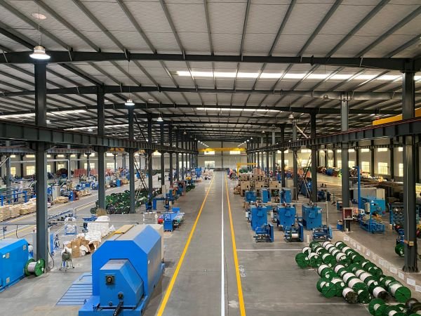
Every drum of mining trailing cable is produced under controlled processes and released against the applicable ICEA S-75-381 and IEC 60502-2 requirements.
Tell us the voltage class, power-core size, sheath option and quantity.
We confirm insulation thickness, screen, sheath compound and the governing standard edition within one working day.
Short sample lengths for machine qualification; stocked constructions ship within a few working days.
15–25 working days lead time, with the 5-minute AC voltage test and batch documentation.
Steel or wooden drum packing, shipping documents and after-sales support.
Tell us the voltage class and power-core size — we reply within one working day.
The more detail you give, the faster and more accurate our quotation. Our engineers reply within one working day.
Thanks — our engineers will reply within one working day.