Professional cable manufacturer

Professional cable manufacturer
Home » Products » Power Cable » Cu/XLPE/SWA/PVC 0.6/1 kV Armoured Power Cable
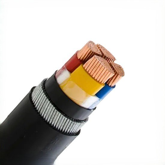
Low-voltage armoured power cable built for routes that get dug up, driven over or gnawed at: copper conductors, XLPE insulation, galvanised steel wire armour and a black PVC over-sheath, in 4 × 4 mm² to 4 × 400 mm² and 2 to 5 cores.
The six numbers an electrical contractor or EPC checks first on an armoured LV power cable — before reading the size table below.
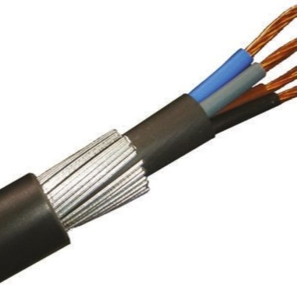
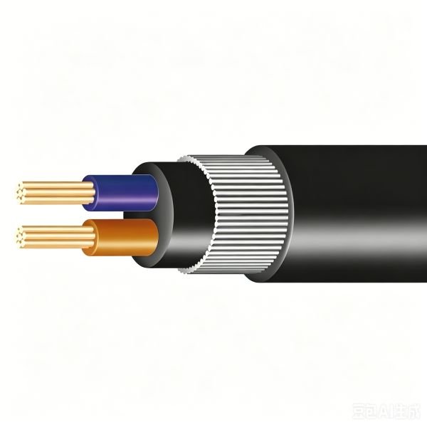
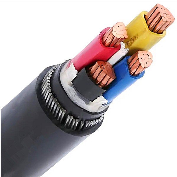
This is the standard low-voltage armoured power cable: plain annealed copper conductors to IEC 60228 Class 2, extruded XLPE insulation rated +90 °C continuous, an extruded bedding, a single layer of galvanised steel wires, and a black PVC over-sheath. That layer stack is the BS 5467 arrangement for 0.6/1 kV cable, and it is also the arrangement covered by IEC 60502 for extruded-insulation power cable at this voltage. The same stack with a halogen-free sheath instead of PVC is BS 6724 — same geometry, same armour, different compound; that version is on its own page.
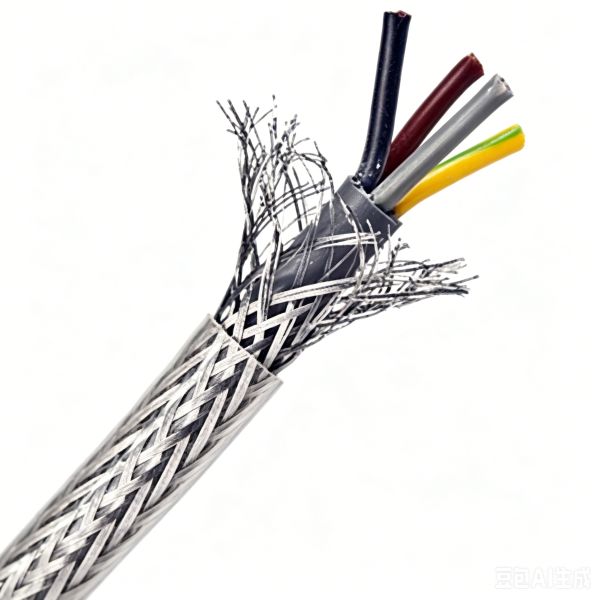
It is worth being precise about the armour, because the phrase "armoured cable" gets used to mean two different things. Steel wire armour is a mechanical layer: it takes radial crushing loads, it lets the cable be pulled without the sheath being asked to carry the whole tension, and it gives a gnawing rodent something harder to get through than a PVC jacket. It is not an EMC screen. At the frequencies that disturb control and instrumentation circuits, a layer of steel wires does close to nothing, and a cable specified as "armoured" on the assumption that it is also screened is a mistake that surfaces later as an intermittent fault. If you need screening, that is a different construction — see the YY/SY/CY Control Cable family for the copper-braid option.
On earthing: the armour can serve as a circuit protective conductor where it is effectively earthed at both ends and the applicable local wiring regulations permit it — but that is an installation decision with a continuity and current-carrying assessment behind it, not a property of the cable. Where a separate protective conductor is required, order a 3 + 1 or 3 + 2 core construction with the PE as a separate core; do not assume a four-core cable contains one.
The size table below is the real one, and it is the same table our engineers quote from. Every core count has its own diameter, weight, armour wire size and current rating, so there is no single "rated amps" for this family. The two current columns are the two sets of reference conditions the manufacturer publishes — in air at 30 °C and direct buried at 20 °C — and they differ by 20–25 %. Size against your route, not against a headline number.
Where the numbers come from matters here. Every diameter, weight, conductor resistance, armour wire diameter and current rating in Table 1 is the nominal value published for this exact construction, and all of it is repeated back on the drawing before the drum is made. Nothing in the table is inferred, and where a value is not published for a construction we leave the cell out rather than filling it with a plausible-looking figure.
For the halogen-free version of the same cable, see the LSZH Armoured Power Cable. For this family in fixed sections, see the 16 mm² 2-core and 4 × 70 mm² pages.
More about the manufacturer: About SORIVO →
Cross-linked polyethylene insulation raises the continuous conductor temperature to +90 °C and the short-circuit allowance to +250 °C, which is where the extra ampacity over a PVC-insulated cable comes from.
A single layer of galvanised steel wires over the extruded bedding. It is there for crushing, pulling and rodent resistance — we will not describe it as a screen.
Plain annealed copper to IEC 60228 Class 2. Larger sections are compacted or sector-shaped, and that shape is published for the size so the termination can be planned.
Conductor, XLPE insulation, bedding, steel wire armour, PVC over-sheath. Each layer has its own thickness in the size table, so nothing is left as "per standard".
The armour and the PVC over-sheath together take the cable outdoors, underground, into ducts, troughs and cable trays where mechanical damage is expected.
1.5 mm² to 400 mm² depending on core count, with 7, 10, 12, 19, 27 and 37 core versions available at the smaller sections for distribution and auxiliaries.
Every completed length is withstand-tested at 3.5 kV AC for 5 minutes, with conductor resistance and insulation resistance measured and recorded.
The same construction with an LSZH bedding and over-sheath to BS 6724 for confined spaces, tunnels, stations and plant rooms where smoke and acid gas are the design driver.
Any route where the cable has to survive the environment rather than being protected from it.
Direct-buried and ducted LV feeders between a transformer, a main board and outbuildings, where the armour is what keeps the cable serviceable after the trench is backfilled.
Sub-mains to MCCs, motor control panels and process equipment inside a plant, on tray or in trench where mechanical damage is likely.
LV connections between transformers, switchgear and distribution boards, including the runs that leave the building and go underground.
Buried and ducted supplies to pumps, valves and aeration equipment, where the joint bay and the pull are the parts that decide the drum length.
Overground and buried distribution that gets walked on, driven over and moved, which is exactly the duty a steel wire armour is specified for.
LV collection and auxiliary power runs at solar, wind and energy-storage sites, outdoors and in cable trench, feeding inverter and transformer stations.
Traction auxiliary and station power where mechanical protection is mandatory and the fire performance requirement usually pushes the design to the halogen-free version of this same cable.
Shore power, crane and dock supplies where abrasion and salt-laden air both have to be survived and the cable is pulled through ducts and over edges.
The complete parameter set — the same data our engineers quote from.
| Cores × size (mm²) | Conductor dia. (mm) | Insulation (mm) | Bedding (mm) | Steel wire dia. (mm) | Overall dia. (mm) | Weight (kg/km) | R20 (Ω/km) | In air 30 °C (A) | Buried 20 °C (A) |
|---|---|---|---|---|---|---|---|---|---|
| 4 × 4 | 2.6 | 0.7 | 0.8 | 0.9 | 16 | 500 | 4.61 | 42 | 39 |
| 4 × 6 | 3.2 | 0.7 | 0.8 | 1.25 | 18 | 750 | 3.08 | 54 | 49 |
| 4 × 10 | 3.8 | 0.7 | 0.8 | 1.25 | 20 | 950 | 1.83 | 75 | 65 |
| 4 × 16 | 4.8 | 0.7 | 0.8 | 1.25 | 22 | 1300 | 1.15 | 100 | 84 |
| 4 × 25 | 5.9 | 0.9 | 1.0 | 1.6 | 27 | 1900 | 0.727 | 127 | 107 |
| 4 × 35 | 6.9 | 0.9 | 1.0 | 1.6 | 30 | 2500 | 0.524 | 158 | 129 |
| 4 × 50 | 9.8 | 1.0 | 1.0 | 1.6 | 31 | 2750 | 0.387 | 192 | 153 |
| 4 × 70 | 11.7 | 1.1 | 1.2 | 2.0 | 37 | 4000 | 0.268 | 246 | 188 |
| 4 × 95 | 13.7 | 1.1 | 1.2 | 2.0 | 41 | 5250 | 0.193 | 298 | 226 |
| 4 × 120 | 15.6 | 1.2 | 1.4 | 2.5 | 46 | 6750 | 0.153 | 346 | 257 |
| 4 × 150 | 17.0 | 1.4 | 1.4 | 2.5 | 51 | 8000 | 0.124 | 399 | 287 |
| 4 × 185 | 19.0 | 1.6 | 1.4 | 2.5 | 55 | 9750 | 0.099 | 456 | 324 |
| 4 × 240 | 22.0 | 1.7 | 1.6 | 2.5 | 61 | 12500 | 0.075 | 538 | 375 |
| 4 × 300 | 24.5 | 1.8 | 1.6 | 2.5 | 68 | 15000 | 0.060 | 621 | 419 |
| 4 × 400 | 27.8 | 2.0 | 1.8 | 3.15 | 78 | 20000 | 0.047 | 721 | 464 |
Overall diameters, weights, conductor resistances and current ratings are the nominal values published for this construction; they are not guaranteed limits and the final values are confirmed on the drawing for the ordered drum length. Conductor resistance is the 20 °C DC value — at the 90 °C conductor temperature of this insulation it rises by roughly 20 %, which is why a voltage-drop calculation must not use the 20 °C figure. The two current-rating columns are the two sets of reference conditions the manufacturer publishes, in air at 30 °C and direct buried at 20 °C; they differ by 20–25 % and neither is a single "rated current". Real ampacity depends on the installation method, ambient or soil temperature, grouping, soil thermal resistivity and burial depth, so please size against the conditions of your route rather than against one number from a catalogue.
| Cores × size (mm²) | Conductor dia. (mm) | Insulation (mm) | Bedding (mm) | Steel wire dia. (mm) | Overall dia. (mm) | Weight (kg/km) | R20 (Ω/km) | In air 30 °C (A) | Buried 20 °C (A) |
|---|---|---|---|---|---|---|---|---|---|
| 2 × 10 | 3.8 | 0.7 | 0.8 | 0.9 | 17 | 650 | 1.83 | 86 | 77 |
| 2 × 16 | 4.8 | 0.7 | 0.8 | 1.25 | 19 | 900 | 1.15 | 115 | 100 |
| 2 × 25 | 5.9 | 0.9 | 0.8 | 1.25 | 23 | 1200 | 0.727 | 149 | 129 |
| 2 × 35 | 6.9 | 0.9 | 1.0 | 1.6 | 26 | 1700 | 0.524 | 185 | 155 |
| 3 × 70 | 11.7 | 1.1 | 1.0 | 1.6 | 32 | 3000 | 0.268 | — | — |
The two- and three-core rows are given at the same 30 °C air and 20 °C buried reference conditions as Table 1, from the same data set. Note that two-core ratings are consistently higher than four-core at the same cross-section — a 2 × 16 mm² cable carries 115 A in air against 100 A for 4 × 16 mm² — because fewer loaded cores share the same surface area. Duct and tray installation, ambient temperature and grouping all move these figures, so use them as the starting point for a sizing calculation and not as the answer to it.
| General Information | |
| Product Name | Cu/XLPE/SWA/PVC 0.6/1 kV Armoured Power Cable |
| Product Family | Copper conductor, XLPE insulated, steel wire armoured, PVC sheathed low-voltage power cable to BS 5467 |
| Reference Standards | BS 5467; IEC 60502 for the 0.6/1 kV extruded-insulation construction; conductor to IEC 60228 Class 2; flame retardance to IEC 60332-1-2. |
| Rated Voltage U₀/U | 0.6/1 kV |
| Electrical Ratings | |
| Rated Voltage U₀/U | 0.6/1 kV |
| Max. Conductor Temperature | +90 °C continuous, the XLPE rating |
| Short-Circuit Conductor Temperature | +250 °C maximum, taken as the IEC 60502-1 short-circuit condition for XLPE-insulated copper cable, limited to 5 s. It is a calculated duty, not a temperature the cable may sit at. |
| Test Voltage | 3.5 kV AC for 5 minutes on the completed cable — the routine withstand test for 0.6/1 kV finished cable |
| Voltage Drop | A first-order estimate is 2 × R20 Ω/km for a single-phase circuit and √3 × R20 Ω/km for a balanced three-phase circuit, using the 20 °C resistance from the table. Add the reactance term and correct the resistance to the operating temperature before using it for a final design. |
| Construction | |
| Conductor | Plain annealed copper, Class 2 stranded and compacted to IEC 60228; larger four-core sizes are sector-shaped |
| Insulation | Extruded XLPE, nominal thickness 0.7–2.0 mm across the range |
| Bedding | Extruded PVC, nominal thickness 0.8–1.8 mm depending on the size |
| Armour | Single layer galvanised steel wires, 0.9–3.15 mm diameter depending on the size |
| Outer Sheath | PVC, black; nominal thickness per the size table |
| Core Identification | Blue, brown for two-core; blue, brown, black, grey for four-core; confirmed against the drawing |
| Environment | |
| Operating Temperature Range | −20 °C to +90 °C — the range published for this construction |
| Minimum Installation Temperature | 0 °C. Below this the PVC bedding and sheath stiffen; warm the drum area or postpone the pull rather than forcing the cable. |
| Bending Radius when Laying | 8 × overall diameter, the manufacturer figure for this construction. The final radius should be confirmed against the applicable standard and the actual installation method. |
| Weather Resistance | Rated good for outdoor and buried service by the manufacturer data sheet. |
| Flame Retardance | IEC 60332-1-2 — single insulated cable vertical flame propagation |
| Rodent and Termite | The steel wire armour is the barrier. It is a mechanical layer, not a chemical one, so it resists gnawing rather than repelling it. |
| Configuration & Logistics | |
| Core Configurations | 1 to 5 cores as standard; 7, 10, 12, 19, 27 and 37 core versions at the smaller cross-sections. Configurations with a separate protective conductor (3 + 1, 3 + 2) are quoted individually. |
| Cross-Section Range | 1.5 mm² to 400 mm² depending on core count — see Table 1 and Table 2 |
| Sheath Options | PVC as standard; halogen-free LSZH to BS 6724 on the separate LSZH version of this cable |
| Standard Lengths | 500 m to 1000 m per drum depending on cross-section; cut lengths on request |
| Packaging | Wooden drum or steel drum; custom drum and marking on request |
| MOQ | 100 m — sample length negotiable |
| Lead Time | 15–30 working days; 5–7 days for stocked configurations |
| Customization | Core count, cross-section, sheath colour, flame-retardant grade, drum type and customer marking |
The standard-based values on this page are limited to what the construction is actually built and tested to: BS 5467 for the armoured 0.6/1 kV arrangement, IEC 60502 for the extruded-insulation construction, IEC 60228 Class 2 for the conductor and IEC 60332-1-2 for the vertical flame test. The 3.5 kV AC / 5 minute figure is the routine withstand test applied to every finished length. The +250 °C short-circuit temperature is a 5-second design condition from the IEC 60502-1 basis for XLPE-insulated copper cable, not a service temperature. Insulation resistance is a manufacturer routine-test value confirmed on the report for the supplied drum. Diameters and weights are nominal and are re-confirmed on the drawing before production — final selection should be based on the installation method, the ambient conditions and the applicable local requirements.
The construction — copper to IEC 60228, XLPE insulation, galvanised steel wire armour and PVC over-sheath — is the BS 5467 arrangement for 0.6/1 kV armoured cable. We quote the standard the cable is built and tested to; we do not write "certified" where the correct statement is "made to". The test certificate and conductor-resistance records for the supplied drum come with the quotation.
Request the test documents →A 3.5 kV AC withstand test for 5 minutes is applied to every completed length and recorded, and the XLPE insulation and PVC sheath are type-tested as a system for the 0.6/1 kV rating. If you need the type-test report for the exact construction you are buying, ask for it by the ordered size and we will send the one that matches.
Request the type-test report →There is no CE certification for cable — CE marking is a manufacturer’s declaration of conformity, and which directive applies depends on the installation. We will not print "CE certified": a Declaration of Conformity and a RoHS declaration are provided on request for the construction supplied, together with whatever national approval documentation the destination market requires.
Request documentation →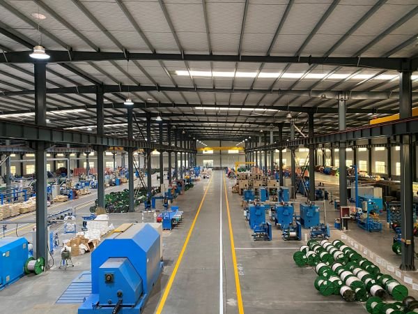
An armoured cable fails at the armour or at the drum end of the process as often as at the insulation, so the release checks cover the layer that is hardest to inspect later.
Tell us the core configuration and cross-section, the sheath type you need (PVC or halogen-free), the installed route and the quantity.
We confirm the core configuration, cross-section, sheath type and any separate protective conductor with you, send the construction drawing for approval, and quote against it — normally within one working day.
Sample for qualification — stocked configurations within a few working days.
Made-to-order lengths are produced against the confirmed drawing; the production window for the size and quantity is confirmed in the quotation, and the routine test is run on every length before the drum leaves.
Drum schedule and shipping documents, plus support through installation — pulling tension and bending-radius guidance for the size and route you have, and the electrical routine-test records for the supplied drums.
Send the core configuration, cross-section, route and quantity — we reply within one working day.
The more detail you give, the faster and more accurate our quotation. Our engineers reply within one working day.
Thanks — our engineers will reply within one working day.