Published: July 8, 2026
PV Connector Failures by the Numbers: What 6,276 Field Samples Reveal About MC4-Compatible Connector Quality
The largest U.S. field study found 6.1% of connectors already past critical failure. An India study across 11 climate zones measured contact resistance increases up to 600%. Here's the data — and what it means for how you specify connectors.
The Connector Problem Nobody Talks About
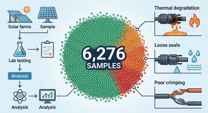
Here's a number that should stop any solar project manager cold: in a 2025 field study by Sandia National Laboratories, 6.1% of the 6,276 photovoltaic connectors they examined had already crossed the critical failure threshold. We're not talking about "less-than-ideal" performance. These connectors exhibited contact resistance above 50 mΩ — a level that puts them on a direct path to resistive heating, housing degradation, and eventually, DC arcing. (Read the study.)
Now pair that with another data point: across Europe, connector failures have been implicated in 24–27% of all solar-related fires. In Germany alone, a review of 180 PV fire incidents traced 24% back to connector problems. And when a connector fails in a large-scale system? The median repair downtime is 191 hours per NREL's analysis of 50,000+ O&M tickets — while the mean (average) downtime reaches 1,579 hours once extreme cases are included. That gap tells you something: most failures are fixed quickly, but the ones that escalate can take a system offline for months.
I've spent the better part of the last decade working with PV interconnection components, and here's the thing I keep coming back to: the connector is the most undervalued component in a solar installation. It costs a fraction of a cent per watt, but when it fails, it takes down an entire string — sometimes the whole system. Let's dig into why, and more importantly, how to make sure it doesn't happen to your project.
6.1%
of field connectors critically failed (>50 mΩ) — Sandia 2025
24-27%
of solar fires linked to connector failures (Europe)
191 hrs
median repair downtime per connector failure (NREL)
600%
contact resistance increase after damp heat in aged connectors
IEC 62852 and UL 6703: What Certification Actually Covers
Before we get into the failure data, let's establish the baseline. IEC 62852:2014 + Amd.1:2020 is the primary international standard for DC connectors in photovoltaic systems. UL 6703 covers the same ground for the North American market. These standards define the electrical, mechanical, and environmental tests a connector must pass to be certified.
But here's what a lot of buyers miss: IEC 62852 certification applies only to a mated pair from the same manufacturer. The moment you mate a Stäubli MC4 plug with a generic compatible socket — even if it fits physically — that certification is void. The same goes for UL 6703. This isn't a technicality; it's a safety issue, and we'll see why when we look at the field data.
| Parameter | IEC 62852 Rating | Notes |
|---|
| Rated Voltage | DC 1100 V (IEC) / DC 1500 V (UL 6703, 2PfG 2330*) | *1500 V in access-restricted systems only |
| Rated Current (4 mm²) | 30–35 A (varies by design) | Tested at 85°C ambient per IEC 62852 |
| Rated Current (6 mm²) | 35–40 A (varies by design) | Tested at 85°C ambient per IEC 62852 |
| Contact Resistance | Initial ≤ 0.30–0.50 mΩ (per manufacturer); Sorivo batch-verified ≤ 0.25 mΩ | ≤ 150% of initial after testing |
| Impulse Withstand Voltage | 12 kV (1000 V systems) / 16 kV (1500 V systems) | Overvoltage category III, pollution degree 3 |
| Temperature Range | -40 °C to +85 °C (ambient) | ULT (Upper Limiting Temperature) 105 °C |
| Ingress Protection | IP65 / IP68 (1 m, 1 h) | Mated condition |
| Safety Class | Class II (DC 1100 V) / Class 0 (DC 1500 V) | Class 0 = basic insulation only, restricted access required per IEC 62852 |
| Flammability | UL94 V-0 | Housing material requirement |
The rated current numbers above assume one critical condition: proper crimping. The IEC 62852 test sequence includes crimp pull-out force verification, but in the field, crimp quality varies wildly. That's where the trouble starts.
Genuine MC4 vs. MC4-Compatible: The Real Differences
Quick clarification: "MC4" is a trademarked product from Stäubli Electrical Connectors (formerly Multi-Contact, Switzerland). The "MC" stands for Multi-Contact and the "4" refers to the 4 mm contact pin. Every "MC4 compatible" or "MC4 compatible solar connector" on the market is a third-party implementation. Some are excellent. Some are dangerous.
Here's how they stack up against what we manufacture at Sorivo:
| Property | Economy / No-Name Generic | Original Stäubli MC4 | Sorivo Quality Grade |
|---|
| Contact Material | Brass, thin tin plating | Tinned copper, MULTILAM technology | Tinned copper, 99.98% purity |
| Contact Resistance | Often > 0.5 mΩ (unstable) | ≤ 0.25 mΩ | ≤ 0.25 mΩ (verified batch test) |
| Housing Material | Polypropylene (cheap, poor UV) | PC/PA blend | PPO/PPE, UL94 V-0 |
| Sealing System | Single O-ring, inconsistent | Dual-seal system | Dual-injection molded, IP68 verified |
| UV Resistance | Minimal stabilizer — embrittles in 3-5 years | High — outdoor-rated polymer | PPO/PPE polymer with UV stabilizer package, outdoor-rated |
| Crimp Compatibility | Poor tolerance — loose or over-crimped | Precision — dedicated die sets | Factory-crimped, pull-force tested per IEC 62852 |
| Certification Scope | Self-declared CE only | TÜV / UL / JET | TÜV-designed per IEC 62852, batch traceable |
| Traceability | None | Lot marking | Meter-marked cable, batch-coded connectors |
| 25-Year Service Life | Unlikely — polymer degrades | Yes — with proper installation | Yes — fully rated for PV system lifespan |
Critical: Even reputable third-party connector brands — which may be physically compatible with the MC4 interface — explicitly state their connectors should not be cross-mated with original Stäubli MC4. UL 6703 certification is only valid for same-brand pairs. Cross-mating voids the certification of both connectors.
What 6,276 Connectors Taught Us About Failure
The Sandia study published in Solar Energy (2025) examined 6,276 connectors harvested from rooftop installations across the United States. The findings are sobering. Beyond the headline 6.1% critical failure rate, researchers identified specific failure indicators that correlate directly with connector quality:
The Failure Cascade
It rarely happens all at once. Connector failure is a chain reaction that feeds on itself:
1Initial defect — A poor crimp, incomplete mating, cross-manufacturer mismatch, or corrosion initiation at the contact interface. Often invisible at installation.
2Contact resistance rises — The defect increases electrical resistance at the connection point. Power dissipation follows P = I²R. A connector that should run at 0.25 mΩ is now at 5, 20, or 50 mΩ.
3Resistive heating accelerates — Internal temperature at the contact surface can exceed 150 °C even when ambient is 30 °C. This thermal stress softens the housing polymer.
4Seal degradation — The O-ring or injection-molded seal loses elasticity. Moisture enters the connector housing. Now you have corrosion plus heat.
5Positive feedback loop — Moisture accelerates corrosion, corrosion increases resistance, resistance generates more heat. Contact resistance can climb 300–600% from the initial value.
6Catastrophic failure — Housing melts, exposing live DC contacts. A DC arc initiates — and unlike AC, a DC arc does not self-extinguish at zero crossing. The result is a sustained electrical fire.
Field Data by the Numbers
| Parameter | Threshold / Finding | Source |
|---|
| Critical contact resistance | > 50 mΩ (6.1% of samples) | Sandia 2025 |
| Failure onset from baseline | ≈ 200% increase | Kapoor et al. 2025 |
| Temperature rise warning threshold | ΔT > 30 °C above ambient | Sandia / EPRI / NREL |
| Permissible increase per IEC 62852 | ≤ 150% of initial value | IEC 62852 |
| Damp heat increase (extreme climate, >6 yr) | Up to 600% | Kapoor et al. 2025 |
| Connectors with >6 yr service in arid/desert regions | 300% increase after thermal cycling | Kapoor et al. 2025 |
A separate study published in IEEE J. Photovoltaics (2024) examined 117 connector specimens using X-ray CT, SEM-EDX, and thermal analysis. They identified fretting, inelastic deformation, and oxidation as the dominant degradation mechanisms at the metal pin interface. Polymer degradation was confirmed by FTIR and TGA analysis — the housing material literally changes its chemical composition over time under thermal stress. (Read the IEEE paper.)
What's telling is that many of the failed connectors in the Sandia study could have their ferrules loosened by hand. That's not a material defect — that's an installation quality problem. And it's entirely preventable.
How to Identify a Quality MC4-Compatible Connector
Based on what the data tells us, here's what I look for when evaluating a connector — whether we're sourcing them at Sorivo or auditing a supplier:
- Contact resistance specification — Ask for the batch test report. Initial contact resistance should be ≤ 0.25 mΩ. Anything higher tells you the contact design or plating is marginal.
- Crimp quality verification — For pre-terminated harnesses, demand pull-force test results per IEC 62852. A 4 mm² conductor should withstand minimum 310 N pull-out force. If they can't provide the data, they haven't done the test.
- Housing material — Polypropylene (PP) is a red flag for outdoor PV use. Look for PPO/PPE, PC/PA, or similar engineering thermoplastics rated UL94 V-0. A simple flame test (yes, you can do this) distinguishes PP from higher-grade materials by burn behavior and smoke odor.
- Seal integrity — IP68 certification means 1 m submersion for 1 hour. But ask: was the test done on mated connectors with the correct cable attached? Some "IP68" connectors are only rated in the unmated condition, which is useless for field applications.
- Marking permanence — Quality connectors have laser- or hot-stamped markings that don't rub off. If you can scrape the polarity symbols off with a fingernail, the connector has no business on a rooftop for 25 years.
- Temperature rise test — A quality connector should show ΔT < 30 °C at rated current. Request the IR camera report from the manufacturer's type test.
The Real Cost of a Connector Failure
I hear this all the time: "It's just a connector. Why pay more?"
Fair question. Here's the math that matters.
A quality MC4 compatible solar connector pair from a reputable manufacturer costs roughly $1.50–$3.00 per connection point. An economy-grade generic might cost $0.40–$0.80. The difference is about a dollar per connector.
Now look at the cost of a failure. NREL's analysis of 837 utility-scale sites found a median repair downtime of 191 hours (roughly 8 days) per connector failure. The mean is higher at 1,579 hours because a small number of catastrophic failures — where the connector melted or started a fire — take months to resolve, skewing the average. Even using the conservative 191-hour figure: for a 10 MW system generating at $0.04/kWh, 8 days of lost production from a single string represents roughly $6,300 in lost revenue. If the failure escalates to a fire, the cost jumps to insurance deductibles, litigation, and reputational damage that dwarfs the component cost entirely.
| Cost Factor | Economy Generic Connector | Sorivo Quality Connector |
|---|
| Per-connector cost | $0.40–$0.80 | $1.50–$3.00 |
| Failure probability (25 yr) | 5–8% (based on field data) | < 0.5% (factory-tested, batch traceable) |
| Lost revenue per string failure | $5,000–$8,000+ (191 hr median downtime) | Negligible |
| System fire risk (cumulative, 25 yr) | Low but non-zero — connector implicated in ~25% of solar fires | Effectively eliminated at the connector level |
| TCO over 25 years (500-connector system) | $200–$400 initially + $5,000–$16,000 expected failure loss | $750–$1,500 total — including zero expected failure loss |
The bottom line: You're not saving money with cheap connectors. You're deferring the cost — with interest — to the O&M budget. A dollar saved at procurement can easily become ten thousand dollars lost during operations. It's really that straightforward.
Why Pre-Terminated Harnesses Reduce the Biggest Variable: Human Error
Sandia's field data identified improper installation as one of the most common root causes of connector failure. Loose nuts, tight wire bending radii, and contamination during field assembly were all documented in the 6,276-connector survey.
This is where a pre-terminated cable harness changes the equation. When you order connectors factory-terminated onto H1Z2Z2-K solar cable:
- Every crimp is performed on a calibrated, die-matched crimp tool — not a $40 off-the-shelf tool from Amazon.
- Pull-force is verified before the harness leaves the factory. You get a test report, not a promise.
- The seal is fully seated and inspected. No partial insertion, no missing O-rings.
- Contact resistance is measured — typically ≤ 0.25 mΩ per pair, verified per batch.
- Custom lengths (from 0.3 m jumpers to 50 m extension cables) and configurations (Y-branch, T-branch) arrive ready to install, reducing field labor time by up to 60%.
Field-crimped connectors are the single largest controllable variable in PV system reliability. Removing that variable is a straightforward decision when you look at the data.
Applications
The connector requirements differ by application. A 1500 V DC ground-mount farm has different thermal and mechanical demands than a residential rooftop. Here's how we think about it:
| Application | Key Consideration | Recommended Connector / Cable |
|---|
| Utility-scale solar farm (1500 V DC) | High string current, long cable runs, high UV exposure | 6 mm² pre-terminated harness, IP68, 1500 V rated |
| Commercial rooftop | Temperature cycling, limited access for maintenance | 4 mm² pre-terminated, dual-seal IP68 |
| Residential PV | Mixed connector brands (panel vs. inverter), space constraints | 4 mm² extension cables with verified MC4 compatibility |
| Solar + BESS (battery storage) | DC coupling, high cyclic current, interconnection with ESS cables | 6 mm² harness, verify cable meets TÜV 2PfG 2642 / UL 4703 if used inside battery enclosure |
| Solar street lighting / off-grid | Low current but exposed to humidity, insects, animals | 4 mm² harness, IP68, sealed at both ends |
Frequently Asked Questions
Q
Can I mate an MC4-compatible connector with an original Stäubli MC4?
Technically they will physically fit, but industry consensus is clear: don't do it. IEC 62852 and UL 6703 certifications are only valid for same-brand mated pairs. Cross-mating different connector brands increases contact resistance, generates heat, and voids the certification of both connectors. The NEC and MCS (UK) both prohibit cross-mating. If your project has mixed connector brands, the safest approach is to standardize on one manufacturer — ideally by using a pre-terminated harness that matches your panels' connectors.
Q
What's the difference between current ratings on MC4-compatible connectors?
The rated current depends on both the connector design and the cable cross-section. Per IEC 62852, a 4 mm² assembly typically rates at 30–35 A at 85°C ambient, while 6 mm² rates at 35–40 A. Exact values vary by manufacturer — connector contact design, housing material, and crimp quality all affect the final rating. For practical purposes, 4 mm² harnesses are common in residential and commercial systems, while 6 mm² is preferred for utility-scale or long-run applications where voltage drop matters more than ampacity alone.
Q
How can I tell if a connector is failing in the field?
Three warning signs: (1) Temperature — use an IR camera or thermal probe. A connector running more than 30 °C above ambient is in the danger zone. (2) Visual discoloration — yellowing or browning of the housing indicates thermal stress. (3) Contact resistance measurement — new connectors typically measure ≤ 0.30–0.50 mΩ (IEC 62852 doesn't mandate a single pass/fail value, only that it stays ≤ 150% of initial after testing). In the field, any reading above 0.5 mΩ warrants investigation, and anything above 50 mΩ is critical per the Sandia threshold. For routine inspection, thermal imaging during peak production hours is the most practical method.
Q
Are MC4-compatible connectors safe for 1500 V DC systems?
Yes — provided they are certified for 1500 V DC (UL 6703 or 2PfG 2330/03.2023). IEC 62852 currently rates MC4-style connectors at DC 1100 V; the 1500 V rating under UL and 2PfG has an additional requirement that the system must be in an access-restricted area. Always verify the voltage rating on the specific connector datasheet, and never assume a connector rated for 1000 V will perform safely at 1500 V — the impulse voltage test jumps from 12 kV to 16 kV, which requires different creepage distances.
Q
How long do MC4-compatible solar connectors last in desert environments?
This depends entirely on material quality. The Kapoor et al. 2025 study tested connectors from 11 climate zones in India and found that connectors in cold arid and desert regions showed the most severe degradation after 6+ years — contact resistance increased up to 600% after damp heat testing. The key is UV-resistant housing material (PPO/PPE or PC/PA, not polypropylene) and a robust sealing system. Quality connectors with proper UV stabilizers in the polymer formulation are designed for 25-year life even in high-irradiance environments.
About the Author
Reviewed by Luo Qiang — Senior Cable Application Engineer, Sorivo
15+ years in industrial and renewable energy cable specification. Member of IEC TC 20 (Power Cables). Previously contributed to cable and connector selection for 500 MW+ solar PV and BESS projects across Asia, Europe, and the Middle East.
Need Help Specifying Solar Connectors for Your Project?
Whether you need pre-terminated harnesses, custom lengths, or technical support on connector selection — our engineering team works directly with project developers, EPC contractors, and distributors worldwide.
Browse MC4-Compatible Connectors & HarnessesRelated Resources
- MC4 Compatible Connector & Pre-Terminated Harness Product Page — Full specifications, models, and ordering options
- 4 mm² Solar Extension Cable with MC4 Connectors — Pre-terminated extension cables for residential and commercial PV
- Solar Cable Installation Best Practices Guide — Bending radius, UV protection, MC4 connector handling, and testing standards
- H1Z2Z2-K 4 mm² Tinned Copper Solar Cable — EN 50618 certified PV cable for use with MC4 connectors
- All Sorivo Cable Accessories — Connectors, glands, terminals, and more
- Renewable Energy Cable Solutions — Complete solar PV, BESS, and wind cable systems