Professional cable manufacturer

Professional cable manufacturer
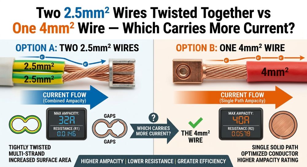
Quick answer: Two 2.5mm² conductors have a total copper area of 5 mm² and a lower combined DC resistance than one 4mm² conductor. But that does not mean they have a simply higher rated ampacity. Parallel conductors must be assessed as an engineered installation — current sharing, installation method, thermal conditions and terminations all matter. For ordinary fixed wiring, one correctly sized cable is normally the simpler, compliant solution.
A question that comes up often: "Two 2.5mm² copper wires twisted together, versus one single 4mm² copper wire — which one carries more current?"
It's one of those questions that seems simple but opens up a whole rabbit hole of physics once you really think about it.
You see, on the surface it's a math problem: two 2.5's give you 5mm² of copper, which is bigger than 4mm². So obviously the twisted pair wins, right?
Well, maybe. And maybe not. The thing is, ampacity — that's engineer-speak for "how much current a wire can safely carry" — isn't just about how much copper you've got. It's about heat. How much the current generates inside the wire, and how fast that heat can escape.
If the question deserves an answer, it deserves a thorough one. So here's the full breakdown — physics, math, real-world gotchas, and all.
Let's start with the basics. Here's what we're working with:
| Property | Single 2.5 mm² | Two 2.5 mm² (Parallel) | Single 4 mm² |
|---|---|---|---|
| Total copper cross-section | 2.5 mm² | 5.0 mm² | 4.0 mm² |
| Conductor diameter | 1.78 mm | 2 × 1.78 mm | 2.26 mm |
| DC resistance (per IEC 60228, Ω/km at 20°C) | 7.41 | 3.705 | 4.61 |
| Outer circumference (cooling surface per mm length) | 5.60 mm | 11.20 mm | 7.09 mm |
| Ampacity (illustrative only — varies with cable type, insulation and installation method) | ~18 A (PVC, in conduit) | Not additive — depends on parallel-conductor design | ~24 A (PVC, in conduit) |
*Ampacity values are illustrative and depend on cable type, insulation and installation method. The two-conductor column is not an additive rating: you cannot simply double or add the ampacity of two parallel conductors.
So right off the bat, two 2.5mm² conductors give you 25% more copper than a single 4mm² — a total area of 5 mm², which should not be treated as a single 5 mm² cable for ampacity selection. Their combined DC resistance per IEC 60228 is about 20% lower, and their combined outer surface area is about 58% larger.
On paper? The twisted pair looks like the clear winner. But here's where it gets interesting.
Here's the core problem — and it's the kind of thing that makes physics beautiful:
When current runs through a wire, the wire heats up. The heat generated follows:
P = I² × R
That means if you double the current, you quadruple the heat. Not double — quadruple. That's why wire sizing isn't linear.
Now, the wire loses heat through its surface. And here's the scaling problem:
Picture this: if you double a wire's diameter, you get 4× the copper but only 2× the cooling surface. That's why bigger wires can't carry proportionally more current — they'd cook themselves.
This is where the two-conductor arrangement looks better on paper. Here's the model:
For a steady-state condition where the wire reaches a stable temperature, the heat balance equation is:
I² × R = h × Asurface × ΔT
Where h is the heat transfer coefficient and ΔT is the temperature rise above ambient.
If we solve for the current ratio between our two candidates:
Iparallel / Isingle 4 = √((Asurf,∥ / R∥) / (Asurf,4 / R4))
Plugging in the numbers:
| Wire setup | R (Ω/km) | Asurf (mm²/m) | Asurf / R | Relative Imax |
|---|---|---|---|---|
| Single 4 mm² | 4.61 | 7,090 | 1,538 | 1.00 (baseline) |
| Two 2.5 mm² (spaced apart) | 3.705 | 11,200 | 3,023 | 1.40× |
| Two 2.5 mm² (tightly twisted) | 3.705 | ~9,520* | ~2,570 | ~1.29× |
*When tightly twisted, roughly 15% of each wire's surface contacts the other, reducing effective cooling area.
So in a simplified heat-balance model, two 2.5mm² conductors can appear to support a higher current than one 4mm² conductor at the same temperature rise. Treat that ratio as an illustrative figure only — a real ampacity value must be taken from the applicable current-rating tables (e.g. IEC 60364-5-52) or an IEC 60287 calculation for the actual installation.
The model is a useful way to see why cross-section alone does not decide ampacity — but it is not an engineering current rating.
Someone with a bit of electrical background might ask: "Doesn't AC current crowd toward the surface of a conductor? Wouldn't that change things?"
Great question. Let's check.
At 50-60 Hz (mains frequency), the skin depth in copper is about 9.3 mm. That's the depth at which current density drops to about 37% of the surface value.
Our 2.5mm² wire has a radius of about 0.89 mm. The skin depth is 10× larger than the wire radius. That means current density at the center is still about 91% of the surface density — essentially uniform.
The rule of thumb: at 50/60 Hz, skin effect is negligible for copper conductors below roughly 1 cm in diameter. Both 2.5mm² and 4mm² are well below that, so the AC resistance is essentially the same as the DC value — it does not affect this comparison.
So for this question, skin effect doesn't change the answer one bit. Same for proximity effect between two twisted wires at these sizes — the effect is so small you'd need lab instruments to measure it.
On paper, two 2.5mm² conductors look better than one 4mm². But engineering is not just physics — it's physics plus reliability, safety and manufacturing reality. Here's where that arrangement loses its appeal.
Here's the thing: two wires twisted together will never share current perfectly equally. One wire will be a hair longer. One termination will have slightly higher resistance. The twist pitch won't be perfectly uniform.
These differences matter. If one conductor ends up carrying more than its share of the total current, it heats up more than the other. Note that for copper the temperature coefficient is positive (about 0.39% per °C), so the hotter conductor has a higher resistance — which tends to reduce its share of the current. That is a mild negative-feedback effect, not a thermal runaway. The real risks are practical: unequal conductor resistance from different lengths, terminations, routing or reactance can still produce an unacceptable current imbalance that pushes one conductor above its rating.
How exactly do you connect two twisted wires into a terminal block or circuit breaker? You've got a few options, and none of them are great:
| Termination method | Drawbacks |
|---|---|
| Both into one screw terminal | One wire may slip out. Contact pressure is uneven. Prone to loosening over time from thermal cycling. |
| Twist together, then into terminal | The twisted section has variable contact resistance. The joint becomes a localized hot spot. |
| Separate terminals, jumpered | This actually works — but requires careful design and a terminal block rated for parallel feeds. Adds cost and extra failure points. |
| Crimped ferrule on both | Possible, but you'd need a ferrule rated for the combined 5mm² cross-section. Rarely done in practice for home wiring. |
Most experienced electricians would look at a twisted-pair termination and call it a fire waiting to happen — and for permanent installations, that assessment is fair.
This part is pretty clear:
The code writers aren't being conservative for no reason. They've seen what happens when parallel small-gauge wires go wrong.
If you're comparing wire options, voltage drop is often a real limiting factor. The table below is an illustrative comparison at assumed load currents (pure DC-resistance model, cos φ = 1) — it is not an ampacity rating.
| Configuration | Current | Voltage drop per 10m (single phase, cos φ=1) | Voltage drop at 20m |
|---|---|---|---|
| Single 4 mm² | 25 A | 1.15 V (0.5%) | 2.30 V (1.0%) |
| Two 2.5 mm² twisted | 32 A | 1.19 V (0.52%) | 2.37 V (1.0%) |
| Single 6 mm² (recommended) | 32 A | 0.99 V (0.43%) | 1.97 V (0.86%) |
For 230V AC system. One-way conductor voltage drop = L × I × R / 1000. Multiply by 2 for total single-phase (line + neutral) drop. R values from IEC 60228 at 20°C. Percentages based on 230V.
| Question | Answer |
|---|---|
| Do two 2.5mm² conductors contain more copper? | Yes — 5 mm² total |
| Does that mean a 5 mm² equivalent ampacity? | No |
| Can parallel conductors share current? | Yes, when properly designed |
| Can you simply add their ampacities? | No |
| Does twisting them together make a 5 mm² conductor? | No |
| Is a single 4 mm² cable normally the simpler solution? | Yes |
| Should parallel 2.5mm² conductors be used for a permanent circuit without design verification? | No |
| Situation | Go with twisted pair? | Better alternative |
|---|---|---|
| Permanent house wiring | Generally not — needs a designed, compliant parallel-conductor arrangement | Single correctly sized cable |
| Temporary event setup (weekend) | Maybe — if properly terminated and monitored | Single 6 mm² H07RN-F rubber cable |
| Science fair / classroom demo | Yes — low voltage, short duration, supervised | N/A — this is the perfect learning scenario |
| 12V DC automotive repair (short run) | Acceptable — low voltage limits risk | Single cable of equivalent size |
| PV string wiring | Not recommended — outdoor UV and thermal cycling worsen joint reliability | Use a single factory-made solar cable — see our solar cable installation guide |
| Factor | Two 2.5 mm² Twisted | Single 4 mm² |
|---|---|---|
| Copper cross-section | 5 mm² — winner | 4 mm² |
| DC resistance | 3.705 Ω/km — lower | 4.61 Ω/km |
| Cooling surface area | 11.2 mm (twisted: ~9.5 mm effective) — better | 7.1 mm |
| Theoretical ampacity | Higher in a simplified heat-balance model — not a rated value | Baseline |
| Current sharing risk | Significant — imbalance can cause hidden overheating | None — single conductor |
| Termination reliability | Poor — multiple methods, all with drawbacks | Standard — well-established |
| Code compliance | Not compliant (NEC) or difficult to justify (BS 7671, IEC) | Fully compliant |
| Long-term reliability | Unknown — thermal cycling degrades twisted joints over time | Proven — decades of field data |
| Labor cost to install | Higher — stripping, twisting, terminating two wires | Lower — one wire, one termination |
| Factory quality assurance | No standard exists for field-twisted pairs | Factory-produced to IEC 60228, full batch traceability |
Here's where the analysis lands:
On the simplified physics: Two 2.5mm² conductors have more total copper area and a lower combined resistance than one 4mm² conductor, which supports a higher current in an idealised heat-balance model. That is illustrative, not an engineering ampacity — the real value must come from the applicable current-rating tables or an IEC 60287 calculation.
As an engineering solution: For permanent wiring, avoid it. The risks — uneven current sharing, unreliable terminations, and the lack of a factory-verified construction — outweigh the theoretical benefits. Codes exist because these lessons were learned the hard way.
For temporary or experimental setups (a science fair project, a quick bench test, a low-voltage DC experiment): Sure, it'll work fine. Just keep an eye on the connection points and don't push it to the limit.
If you're comparing these two options: it's a genuinely good question to work through. It touches on resistance, heat transfer, surface-area-to-volume ratios, and the gap between theoretical physics and practical engineering — all in one simple setup. Working through it properly beats relying on a rule of thumb.
Can I parallel two 2.5mm² wires for a 32A EV charger circuit?
For a fixed installation, this is not recommended. A single cable is simpler and eliminates the current-sharing risk. For a 22kW three-phase charger pulling 32A per phase, a correctly selected 6mm² SWA cable is a common solution — the final size should still be verified from the installation conditions and voltage-drop requirements.
Does twisting direction affect current capacity?
Not in any meaningful way for 50/60 Hz AC or DC. The twist pitch would need to be on the order of centimetres at megahertz frequencies to matter. At mains frequencies, twisting is purely mechanical — it keeps the wires together and can reduce electromagnetic interference in signal applications, but it doesn't change ampacity; any measured difference is within normal measurement scatter.
What if I use two different wire sizes — say 2.5mm² and 1.5mm²?
This makes the current-sharing problem worse. The smaller wire has higher resistance per meter, so it carries less current — but the heat it generates is concentrated in a smaller mass with less surface area to shed it. The thin wire can overheat even when the total current seems reasonable. Best practice: if you ever parallel wires, they must be identical in material, cross-section, and length.
Does tinning the twisted ends with solder help the termination?
It actually makes things worse in a screw terminal. Solder creeps under pressure and heat — the connection loosens over time as the solder deforms. Plus, solder has higher resistivity than copper, so the termination becomes a localized hot spot. For crimped connections, tinning is also not recommended — the solder creates a brittle interface that can crack under vibration or thermal cycling.
What if I'm working in a high-ambient-temperature environment, like a Middle East solar farm?
High ambient temperature is a double blow for twisted pairs: not only does the copper resistance increase (about 20% higher at 70°C vs 20°C), but the reduced temperature gradient between the wire and the air means less effective cooling. In an outdoor PV application where ambient can hit 50-55°C, a twisted pair would need significant derating. This is exactly why EN 50618 solar cables are designed as single-conductor, factory-manufactured products with 25-year thermal lifetime ratings — not field-twisted improvisations.
What's the safe current for two 2.5mm² wires twisted together in free air?
For a conservative estimate, take the ampacity of a single 2.5mm² in free air (~25-30A for PVC insulated) and multiply by about 1.6 to 1.7 (not 2.0) to account for mutual heating and derating. That gives roughly 40-50A total. This is an estimate, not a design value. If you need that much current for a permanent installation, use a properly sized single cable — it'll be safer, code-compliant, and likely cheaper in total installed cost.
At SORIVO, every cable we ship — from 1.5 mm² to 400 mm² — is factory-tested to international standards (IEC, EN, TÜV, UL) with full batch traceability. No field-twisted workarounds needed.
We've been in the cable business for over 15 years. Our team works with power engineers, contractors, and renewable energy developers worldwide to specify the right cable — not the improvised one. If you're designing a system and aren't sure about the right cable size, we're happy to help you get it right the first time.
Professional customized cable solutions — 7×24×365 support
| Standard | Title / Purpose |
|---|---|
| IEC 60228 | Conductors of insulated cables — cross-section and DC resistance limits |
| IEC 60287 | Electric cables — calculation of continuous current rating (ampacity) |
| IEC 60364-5-52 | Low-voltage electrical installations — cable selection and ampacity tables |
| NEC 310 (NFPA 70) | National Electrical Code — conductor ampacity and parallel conductor rules |
| BS 7671 | IET Wiring Regulations — UK requirements for conductor sizing and paralleling |