Professional cable manufacturer

Professional cable manufacturer
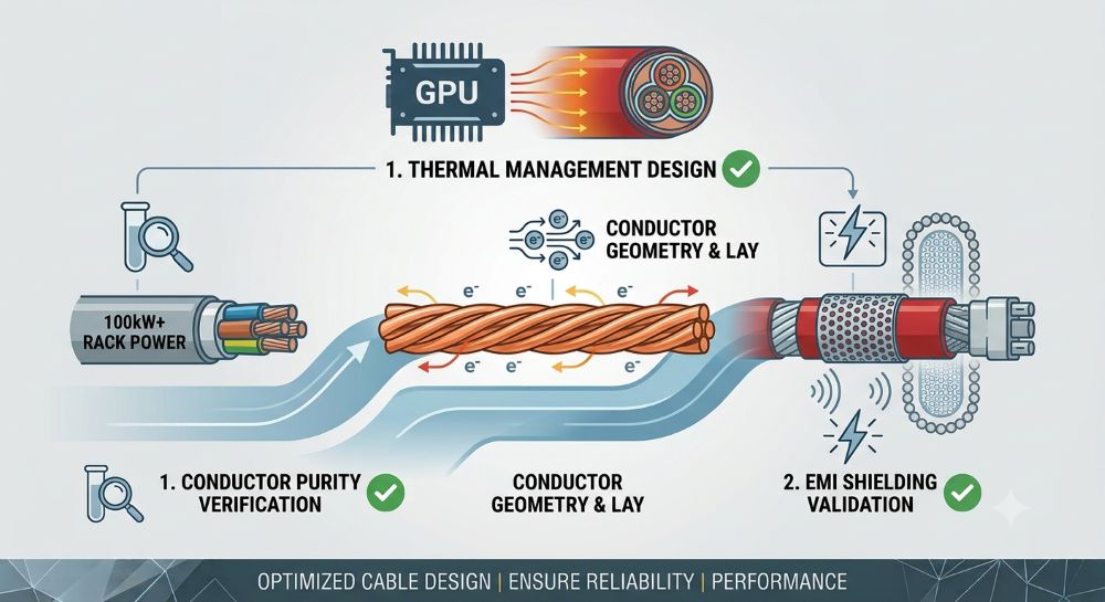
Here's a number that keeps me up at night: 480 amps.
That's how much current you need at 208V to deliver 100kW to a single GPU rack. A rack the size of a refrigerator. And we're not talking about 100kW as some future projection — NVIDIA's GB200 NVL72 already draws 120kW per rack today, and the Vera Rubin NVL144 roadmap targets 600kW by 2027.
The cables that feed these racks are no longer an afterthought. They're a first-order engineering constraint. At 480A, you're looking at conductors the thickness of a garden hose — per phase. Multiply that across hundreds of racks and the copper alone weighs tons. The heat those cables generate inside trays and conduits can raise ambient temperatures by 15-20°C, cooking nearby electronics.
Building on our general AI data center cable selection guide, this article goes deep on the three cable challenges that every designer is grappling with right now: thermal management at extreme power densities, EMI control in electrically noisy GPU environments, and optimizing the physical layout of power and fiber when every square inch of rack space is spoken for.
Everyone talks about GPU thermal management. Fewer people talk about the fact that power cables themselves are significant heat sources at AI-scale currents.
Let's run the numbers on a single 100kW rack fed at 208V, 480A through three parallel 500 kcmil conductors per phase:
Ploss = 3 × I² × R × L
For a 30-meter feeder run of 500 kcmil copper (R ≈ 0.066 Ω/km at 90°C):
That's 273 kW of heat that your cooling system has to remove, generated inside cable trays, under raised floors, and in ceiling plenums where airflow is already restricted.
The problem goes deeper than just I²R heat. Standard PVC-insulated cable is rated from 60°C (TW) to 90°C (THHN) depending on type, with wet-location ratings typically at 75°C. XLPE is rated for 90°C continuous with 105°C emergency overload. But here's what happens in a real AI data center:
I've seen undersized power feeders in AI clusters reach conductor temperatures of 105-110°C — past the emergency overload rating of standard XLPE. The insulation doesn't fail immediately. But every hour at those temperatures consumes days of thermal life.
If you take one thing from this article, let it be this: voltage is the most powerful tool for solving AI data center cabling problems.
| Voltage | Current for 100kW | Conductor size per phase | Relative copper weight | Cable heat (I²R) |
|---|---|---|---|---|
| 208V AC (single-phase) | 480A | 2 × 500 kcmil parallel | 100% (baseline) | 100% |
| 415V AC (3-phase) | 139A | 1 × 4/0 AWG | ~35% | ~30% |
| 480V AC (3-phase) | 120A | 1 × 4/0 AWG | ~30% | ~25% |
| 800V DC | 125A | 1 × 2/0 AWG | ~20% | ~15% |
Table notes: 208V row uses single-phase (common for US PDU distribution); 415V and 480V rows use 3-phase (standard for high-power AI racks). Conductor sizes per NEC ampacity tables at 75°C, 30m feeder length. 800 VDC data from Enteligent white paper (Feb 2026). Moving from 208V to 800VDC reduces copper requirements by 50-80% and cuts cable heat generation by 85%.
The growing consensus among AI data center designers: 208V is a dead end for high-density AI. The 415V/480V three-phase architectures that are standard in much of the world are becoming the baseline, and 800V DC distribution is on the horizon. Each voltage step-up halves the current — and quarters the I²R losses.
The 2026 National Electrical Code introduced several updates that AI data center designers need to know:
| NEC Requirement | What It Means for AI Racks | Impact |
|---|---|---|
| 125% continuous load factor (Art. 215.2 for feeders) | A 400A GPU rack feeder derates to 320A continuous — forces upsizing | Adds 1-2 standard sizes to every feeder |
| 12" vertical clearance between stacked cable trays (NEC 392, 2026 ed.) | Prevents "heat-soak" between tray layers in dense installations | Increases tray footprint by 30-50% |
| 24" working clearance with doors open at 90° | PDU and cable routing paths must leave access space | Eliminates tight-cramped cable layouts |
| Expanded arc-flash labeling on all distribution | Every PDU and feeder panel needs incident energy analysis | Drives design toward higher voltage / lower current |
| ESS classification (Art. 706) for large battery banks | UPS lithium banks now under stricter UL 9540 rules | Affects backup power cable routing and separation |
The 2026 code update is effectively telling AI data center designers: you can't cram cables into every available space anymore. You need to plan for thermal separation, access, and safety labeling from day one.
Now let's talk about the problem that doesn't show up on thermal cameras.
An AI training cluster is an electromagnetic nightmare. Hundreds of GPU nodes switching at high frequencies. Dozens of power supplies generating harmonic currents. High-speed data links running at 400G or 800G between nodes. And every power cable in that environment acts as both an antenna (radiating EMI) and a receptor (picking up noise from other sources).
In my experience, the three most common EMI failure modes in AI data centers are:
| Strategy | Effectiveness | Implementation Notes |
|---|---|---|
| Steel conduit for power feeders | Up to 95% EMF reduction at 60 Hz | Rigid steel conduit outperforms aluminum (10%) and non-metallic (0%). Required for any power cable within 1m of data cables. |
| Power/data separation ≥ 30cm | Essential for crosstalk prevention | Cross at 90° when crossing is unavoidable. Never run power and data in parallel for more than 2m. |
| Foil + braid shielded power cables | 30-40 dB noise reduction | Combined shielding (foil for HF, braid for LF). Ground shield at one end only to avoid ground loops. |
| Star grounding topology | Eliminates ground loops | Single-point ground reference with resistance < 1 Ω. All racks bonded to the same ground plane. |
| Ferrite cores on PDU feeds | Suppresses common-mode noise | Install at PDU input and output. Effective for 1-100 MHz switching noise from UPS and PSUs. |
| Segregated cable trays | Physical isolation | Dedicated trays for power (bottom), copper data (middle), fiber (top). Minimum 15cm vertical separation. |
Not all shielded cables are created equal. Here's what I recommend for different parts of the AI data center power chain:
| Application | Recommended Cable Type | Why |
|---|---|---|
| Main feeder to AI hall | Armoured XLPE/SWA/LSZH with overall shield | Steel wire armour provides magnetic shielding (low freq); LSZH jacket protects equipment in fire |
| PDU to rack busway | Flexible shielded cable, foil + braid, LSZH | Flexibility for routing in tight overhead spaces; combined shielding for broad spectrum |
| Power inside rack | Individual shielded conductors in steel conduit | Maximum isolation for sensitive GPU nodes; steel conduit is the gold standard |
| Data + power hybrid (overhead tray) | Separate trays: power bottom, fiber top | Never mix in same tray — magnetic coupling from power cables induces noise in data lines |
When you're designing the cable plant for an AI data center hall with 200+ racks at 100kW each, the layout decisions you make affect everything — thermal performance, EMI, maintenance access, and future scalability. Here's a framework I've developed from real deployments.
I recommend dividing the overhead cable plane into three distinct zones:
| Zone | Contents | Height from floor | Key Requirement |
|---|---|---|---|
| Upper | Fiber optic trunk cables (MPO/MTP, 96F-288F) | Top tray (highest) | Minimum bend radius R ≥ 10× cable OD; separate from power by ≥ 30cm |
| Middle | Copper data cables (Cat6A, DAC, InfiniBand) | Middle trays | Shielded cable only; keep under 30m to avoid signal degradation |
| Lower | Power feeders (415V/480V to rack PDUs) | Bottom tray (lowest) | Bonded steel tray with cover; maintain 12" vertical clearance to next tray |
Vertical zone separation prevents the three main failure modes: thermal coupling (heat rises from power cables into data), EMI coupling (magnetic fields from power induce noise in data), and maintenance accidents (technicians working on power don't disturb fiber).
Here's something that catches many designers off guard: cable weight. A single 100kW rack fed at 208V needs roughly 500 individual conductor terminations (power + data + control + fiber). The total cable weight per rack is about 450-680 kg (1,000-1,500 lbs).
For a 200-rack AI hall: 90-136 metric tons of cable. That's not just a structural loading concern — it affects tray sizing, ceiling support requirements, and fire stop ratings.
The solution path: higher voltage architectures reduce conductor cross-section and weight. Moving from 208V to 415V cuts cable weight per rack by roughly 65%. That's the difference between needing reinforced ceiling supports and using standard trapeze hangers.
The 2026 NEC requirement (Article 392) for 12" vertical clearance between stacked cable trays has a direct impact on layout density. Here's what it means in practice:
| Parameter | Standard / Economy | Sorivo Premium (AI-Grade) |
|---|---|---|
| Conductor | Bare copper or CCA (higher resistance, oxidizes) | Tinned copper, IEC 60228 Class 5 — corrosion-resistant, stable resistance |
| Insulation | PVC (60-90°C by type; wet rated 75°C max) or standard XLPE (90°C) | LSZH XLPE — 90°C continuous, 125°C short-term overload, low-smoke zero-halogen |
| Shielding | Single foil or no shield | Foil + tinned copper braid, coverage ≥ 85%, transfer impedance ≤ 25 mΩ/m at 30 MHz |
| Armour | None or thin wire | SWA (steel wire) for magnetic shielding — 95% EMF reduction at 60 Hz |
| Flame retardance | IEC 60332-1 only (single vertical) | IEC 60332-3 Category C or D (bunched flame test) + IEC 60754 (zero halogen) |
| Certification | Self-declared CE | TÜV / UL / BASEC / KEMA third-party verified |
| Traceability | No meter marks | Meter-marked every meter, batch-coded, traceable to raw material lot |
| Design life in AI environment | 5-10 years (degradation from sustained heat) | 25+ years (verified by IEC 60216 Arrhenius thermal aging) |
| Scenario | Recommended Cable Type | Key Sizing Consideration |
|---|---|---|
| Main feeder — utility to AI hall (480V, 2000A+) | CU/XLPE/SWA/LSZH armoured power cable | Parallel runs per NEC 310.10(H); ≥ 1/0 AWG per conductor; 125% continuous derating |
| PDU to rack busway (415V, 100-200A) | Flexible shielded cable, foil + braid, LSZH jacket | Check bending radius for flexible cable; maintain shield continuity through connectors |
| Inside-rack GPU power (48V or 400V DC bus) | Individual shielded conductors in steel conduit | Conduit bonding at both ends for ground integrity; ferrite beads on each conductor at PSU entry |
| Overhead fiber backbone (400G/800G) | OS2 single-mode MPO/MTP trunk, 96-288F | Minimum 30cm separation from any power cable; maintain bend radius ≥ 10× OD |
| Liquid-cooled rack (rear-door HX or direct-to-chip) | Cables with fluid-resistant LSZH jacket | Verify jacket compatibility with dielectric coolant; use cable tie materials rated for coolant exposure |
Can I use standard PVC power cable in an AI data center?
I'd strongly advise against it for any power distribution above 30A. PVC is rated for 60-70°C continuous, but AI racks create sustained thermal loading that pushes conductor temperatures well past that. We've measured 105°C+ on undersized feeders in training clusters. The halogen gas released by burning PVC also poses a serious risk to expensive GPU equipment in a fire. LSZH (low-smoke zero-halogen) cable is increasingly mandated in data center codes for good reason — it protects both equipment and human life.
How much separation do I need between power and data cables for AI racks?
TIA-942 and ISO 3010 both specify a minimum of 30 cm (≈12 inches) between power and data cables. In AI deployments with 100kW+ racks, I'd recommend increasing that to 45-60 cm for power feeders above 200A. The magnetic field strength around a conductor carrying 400A is roughly 4× that of a 200A conductor at the same distance. If space constraints make separation impossible, use steel conduit for the power run — it provides up to 95% EMF reduction at 60 Hz.
Should I design for 208V or 415V/480V in my AI data center?
If you're building new: 415V or 480V three-phase, without question. The math is simple — 100kW at 208V needs 480A, requiring massive parallel conductors and generating over 1.3 kW of heat per 30m feeder. At 415V, the same power needs only 139A — a single 4/0 AWG conductor per phase. The cable weight drops by 65%, I²R losses drop by 70%, and you eliminate the need for step-down transformers at every row of racks. The industry consensus is clear: 208V is a dead end for AI-scale power density.
What's the best grounding strategy for EMI control in GPU clusters?
A star grounding topology with single-point ground reference and resistance below 1 Ω. Every rack, PDU, and cable tray bonds back to the same ground plane. This eliminates the ground loops that are the #1 cause of mysterious intermittent EMI problems in AI clusters. For shielded cables, ground the shield at the source end only — grounding at both ends creates a loop that actually amplifies low-frequency magnetic coupling. And don't forget about bonding across cable tray sections: use bonding jumpers at every joint to maintain electrical continuity.
What ampacity derating factor should I use for cable trays serving AI racks?
Start with the NEC requirements: 125% of the calculated load for continuous operation (Article 220.87). Then add a tray fill derating: for 4-6 current-carrying conductors in a tray, the adjustment factor is 0.80 per NEC Table 310.15(B)(3)(a). Combined: your 400A circuit derates to 320A × 0.80 = 256A effective capacity. This is why most AI data centers end up sizing feeders 2-3 standard sizes above what a simple ampacity table would suggest. Always model the actual thermal conditions — ambient temperature near AI rack exhausts can be 20-30°C above the 30°C table baseline.
Is 800V DC practical for AI data center power distribution?
The short answer: it's coming, and faster than most people expect. Enteligent's 2026 white paper shows that 800V DC distribution for AI data centers reduces copper requirements by 50-80% and cuts cable heat generation by roughly 85% compared with 208V AC. Major semiconductor vendors (TI, onsemi, ADI) are all releasing 800V DC-capable power components. The main barrier today is the lack of standardized DC connectors and protection devices at scale — but that gap is closing rapidly. For greenfield AI data centers starting construction in 2027+, 800V DC should be on the roadmap.
Microsoft is also exploring high-temperature superconducting (HTS) cables for zero-resistance power distribution. HTS cables can carry the same power with a 10× reduction in size and weight. The cryogenic cooling requirement remains the challenge, but the economics are becoming viable as rack power demands surge toward 1 MW.
AI data center cabling isn't plumbing anymore — it's a strategic design decision that affects power efficiency, thermal performance, signal integrity, and scalability. The difference between a well-designed cable plant and a rushed one can be 5-8% in PUE, countless hours of training-job interruptions, and millions in avoided rework when you scale from 100 racks to 1,000.
At Sorivo, we've been manufacturing power cables for over 15 years — including LSZH armoured cables, flexible shielded feeders, and high-temperature designs suitable for AI data center environments. Every reel is tested to IEC, EN, TÜV, or UL standards with full batch traceability.
Professional customized cable solutions — 7×24×365 support
| Standard | Title / Purpose |
|---|---|
| NEC 2026 (NFPA 70) | National Electrical Code — Articles 215.2 (continuous load sizing), 310.10(H) (parallel conductors), 392 (cable trays), 706 (ESS) |
| TIA-942 | Telecommunications Infrastructure Standard for Data Centers — power/data separation, cabling topology |
| ISO/IEC 24764 | Information technology — Generic cabling systems for data centres — power/data separation, EMI mitigation |
| IEC 60228 | Conductors of insulated cables — resistance limits and stranding classes |
| IEC 60332-3 | Bunched flame spread test for vertical cables |
| IEC 60754 | Halogen gas evolution from cable materials |
| IEC 60216 | Electrical insulating materials — Thermal endurance properties (Arrhenius thermal aging) |
| IEC 60287 | Electric cables — calculation of continuous current rating (ampacity) |