Professional cable manufacturer

Professional cable manufacturer
Standards referenced: EN 50565-1 / IEC 60502-1 / IEC 60502-2 / HD 603-S1 / TÜV 2PfG 2577 / IEEE 576 / ICEA S-93-639 / GB 50168-2018
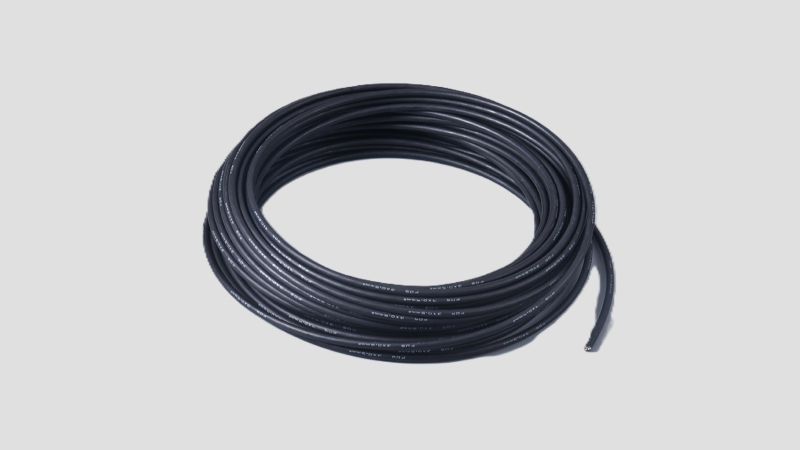
Every cable installation starts with a bend. Off the drum — bend. Through a tray corner — bend. Into a cabinet terminal — bend. Nobody has time to grab a protractor before every single bend on site. Honestly, when I was in the field, I didn't either.
But here's the thing — this most routine of actions creates more hidden failures than almost anything else. I've seen control cabinets start intermittent faulting within six months of commissioning. Three days of troubleshooting later, we found the drag chain cable had fatigued and fractured internally at a bend radius of 5D. I've also seen a PV plant after three years of operation — DC cable sheaths had cracked at turning points and let moisture in. Insulation resistance dropped from 500 MΩ down to 0.5 MΩ. When we cut it open, the bend was pressed hard against a sharp-edged metal tray corner.
Let me be blunt: getting the bending radius wrong doesn't mean you "might" have problems — it means you will shorten the cable's service life. Some failures show up during warranty. Others hit in year three, year five. For 25-year design-life projects like solar farms, wind turbines, and BESS storage, one bad bend can turn into a replacement cost 5–8 times the original installation cost a decade later.
This guide covers bending radius requirements across the full spectrum — from 0.6/1 kV low-voltage cables to 35 kV medium-voltage single-core, from standard control cables to 10-million-cycle drag chain robot cables. I'll also dig into mechanical stress — because bending radius is just the surface. What actually kills cables is the sidewall bearing pressure and conductor tensile stress at the bend. By the end you should be able to answer:
Why can't every cable bend the same way? It comes down to how the cable is put together. These aren't arbitrary rules — they come directly from the cable's physical build.
When a cable bends, the outer side of each conductor strand experiences tension and the inner side compression. IEC 60228 defines the conductor classes, and each behaves differently:
| Conductor Class | Construction | Bend Characteristic | Typical Application |
|---|---|---|---|
| Class 1 | Solid round | Stress concentrates; largest min. bend radius | Fixed, rarely bent |
| Class 2 | Stranded / compact stranded | Better than solid, but strands are thick — limited fatigue life | Fixed power cables |
| Class 5 | Fine wire stranded | Small strand diameter, flexible — min. bend radius down to 4–6D | Mobile equipment, PV cables |
| Class 6 | Ultra-fine wire stranded | Highest flexibility — can reach 3–4D | Drag chain cables, robot cables |
That's why a drag chain cable can bend at 4–5D while a large single-core power cable needs 20D. It's not just about outer diameter — the conductor structure itself pretty much decides how tight you can go.
The stiffness and low-temperature brittleness of insulation materials also directly affects bend capability:
Every additional metallic layer — copper tape screen, steel wire armour (SWA), aluminum tape screen — reduces bendability. The principle is simple: metal layers undergo irreversible plastic deformation when bent too far. Over-bending causes screen wrinkling and fracture, or permanent armour deformation.
Here's the big picture — I've pulled together data from all the major standards in one place. You won't find a more complete cross-reference in any single standard document.
| Standard / Application | Cable Type | Install / Dynamic | Static | Notes |
|---|---|---|---|---|
| EN 50565-1 | Fixed cable D ≤ 8 mm | 4D | 4D | Can go to 2D at termination with former |
| EN 50565-1 | Fixed cable 8 < D ≤ 12 mm | 5D | 5D | Termination: 3D with former |
| EN 50565-1 | Fixed cable D > 12 mm | 6D | 6D | Termination: 4D with former |
| EN 50565-1 | Flexible — free movement | 4–6D | — | Thermoset (XLPE/rubber) more flexible than thermoplastic (PVC) |
| EN 50565-1 | Flexible — reeling/pulley | 8–12D | — | Highest mechanical load at pulley deflection |
| IEC 60502-1 | 0.6/1 kV single-core (unarmoured) | 15D | — | LV power cable baseline |
| IEC 60502-1 | 0.6/1 kV multi-core (unarmoured) | 12D | — | — |
| IEC 60502-2 | 3.6/6–21/35 kV single-core | 20D | — | MV XLPE insulated |
| IEC 60502-2 | 3.6/6–21/35 kV three-core | 15D | — | — |
| HD 603-S1 | No metallic screen (Class 2) | 12D | — | European distribution standard |
| HD 603-S1 | With metallic screen (Class 2) | 16D | — | Screen presence reduces bendability |
| HD 603-S1 | No screen (Class 5) | 8D | — | Flexible conductor advantage |
| HD 603-S1 | With screen (Class 5) | 12D | — | — |
| ICEA S-93-639 | 5–46 kV shielded cables | 12D (single) / 7D (assembly) | — | North America: use whichever is larger |
| TÜV 2PfG 2577 | Robot cable — drag chain test | 6D | — | 5 million cycles baseline |
| Robotic grade (manufacturer) | Super-flex drag chain cable | 4–5D | — | 10+ million cycles |
| Robot arm cable | 10M-cycle torsion + bending | 2.5–3D | — | 2PfG 2577 90° flex test at 2.5D |
| IEC 62930 | PV cable H1Z2Z2-K | 5D | 4D | Small cross-sections (≤4 mm²) may allow 4D per manufacturer data |
| GB 50168-2018 | Power cables (China) | 10–20D | — | Ranges by insulation and armour type |
If you only look at one table, make it this one. That said, understanding the logic behind the numbers matters more than memorizing them.
You'll see this one all the time — building electrical, industrial plants, substation auxiliary supplies. IEC 60502-1 sets the baseline at 15D for single-core and 12D for multi-core. But there's a detail people tend to overlook:
For LV power cables, check the CU/XLPE/SWA/PVC 0.6/1kV armoured power cable for specific outer diameter data.
This is a completely different game. A 1×400 mm² 26/35 kV XLPE single-core cable can easily hit 90 mm outer diameter. At 20D per IEC 60502-2, the minimum bending radius is nearly 1.8 metres.
I'll be honest — on-site, this requirement is often hard to meet. Cable trenches aren't wide enough, cabinet entry space is tight. That's just reality. Here's the thing though:
PV cables are the poster child for flexible cables. EN 50618 requires Class 5 conductors with a minimum bend radius of 5D (small cross-sections ≤4 mm² may allow 4D per manufacturer data). On real projects:
For certified PV cables, see the H1Z2Z2-K 4mm² TÜV solar cable range.
This one's a different beast entirely — not just bending, but repeated bending hundreds of thousands or millions of times.
Per TÜV 2PfG 2577:
Here's what a lot of people miss: a drag chain test doesn't just check "can it bend to this angle." It checks "how many times can it bend at this angle before breaking." So the bend radius for a drag chain cable is always packaged with an expected service life — a supplier's 5D/10M-cycle and 5D/500K-cycle are completely different products at different price points.
| Grade | Flex Life | Bend Radius | Typical Use |
|---|---|---|---|
| Standard flexible | Under 100K cycles | 6–10D | Fixed, occasional movement |
| Medium flexible | 300–500K cycles | 6–8D | Low-frequency automation |
| High flexible | 1M+ cycles | 5–6D | Standard drag chain systems |
| Super flexible | 5M+ cycles | 4–5D | High-speed / high-acceleration drag chain |
| Robotic grade | 10M+ cycles | 2.5–4D | Industrial robot arms |
So when selecting a drag chain cable, don't just look at the bend radius number — ask "at how many cycles?" 5D at 1M cycles and 5D at 10M cycles aren't the same thing.
For industrial automation applications, see SORIVO's industrial automation cable solutions including high-flex and robot-grade cables.
Right, all the bend radius numbers are on the table. But guess what? Insufficient bend radius is just the symptom. What actually destroys cables is the mechanical stress generated at the bend — specifically two things: cable pulling tension and sidewall bearing pressure (SWBP).
Most people focus entirely on memorizing "15D vs 12D" and completely miss the tension variable. Yet it's the tension level that determines whether the same cable at the same bend angle will fail or survive.
SWBP formula is simple — but the implications are not:
What this means in practice: higher tension + tighter bend = much higher sidewall pressure. Because SWBP is inversely proportional to radius — halve the bend radius and you double the pressure. It's not an exponential relationship, I know, but it's just as dangerous on site.
| Cable Type | Max Allowable SWBP (MASP) | Source |
|---|---|---|
| Multi-core power / ≥ 6 AWG single-core | 7,300 N/m (500 lb/ft) | ICEA / IEEE 576 |
| Control cables / ≤ 8 AWG single-core | 4,380 N/m (300 lb/ft) | ICEA / IEEE 576 |
| Armoured cables | Typically 4,380 N/m or lower | Manufacturer-specified |
| Instrumentation cables | 4,380 – 7,300 N/m | Depends on construction |
Let's run the numbers. You're pulling a 1×240 mm² copper XLPE armoured cable — conductor cross-section 240 mm². Copper conductor max allowable tension is about 5 kg/mm² (≈ 49 MPa), so max tension ≈ 240 × 5 = 1,200 kg ≈ 11,760 N.
Now picture that cable going around a tray bend with only a 1-metre radius. You pull hard — what happens?
SWBP = 11,760 / 1.0 = 11,760 N/m — that's 1.6 times the 7,300 N/m limit. The sheath and insulation at that point are crushed. It'll fail within a few years.
Two ways out: either increase the bend radius (R ≈ 1.61 m → SWBP ≈ 7,300 N/m — right at the limit), or reduce pulling tension (pull in shorter sections, add more lubrication). Usually, doing both is the most practical approach. For a safer margin, aim for R = 1.7 m → SWBP ≈ 6,920 N/m.
Now you see why MV cable route designs call for bend radii of 1.5–2 metres or more — it's not an arbitrary number from the designer. It's calculated from sidewall pressure.
Beyond bend radius, tension itself is a critical mechanical stress parameter:
| Parameter | Copper Conductor | Aluminium Conductor | Notes |
|---|---|---|---|
| Max pulling tension (conductor) | 5 kg/mm² (49 MPa) | 3 kg/mm² (29 MPa) | Use pulling eye |
| Max pulling tension (armour) | 15 kg/mm² (armour section) | — | Steel wire armour can take more |
| Stocking grip | Must not exceed sheath strength | — | Grip length: 750–1000 mm |
| Max pulling speed | 5–15 m/min | 5–15 m/min | IEEE 576 recommendation |
| Friction coefficient (dry) | 0.4–0.5 | — | — |
| Friction coefficient (lubricated) | 0.15–0.35 | — | Lubricant makes a huge difference |
Honestly, knowing the standards cold doesn't help if nobody checks on site. I've been on too many projects where the technical specification was beautifully written — and the installation crew had never read it. The final sign-off? "Bent it by eye. Looks fine."
So here's a practical acceptance checklist you can print and take to site:
| # | Check Item | Acceptance Criteria | Tool |
|---|---|---|---|
| 1 | Bend radius compliance | Measured radius ≥ minimum per cable type (see table above) | Bend radius gauge / calliper + calculation |
| 2 | Visual damage at bends | No sheath wrinkles, indentations, or cracks; screen/armour undeformed | Visual inspection |
| 3 | Insulation resistance test | ≥ 100 MΩ at 20°C (XLPE, per IEC 60502-1); ≥ 0.5 MΩ per circuit (LV) | Megohmmeter (2500V / 1000V) |
| 4 | Sheath continuity | No punctures, cuts, or exposed copper | Visual + spark test if available |
| 5 | Screen/armour bonding | Continuity resistance < 10 Ω per 1,000 ft | Multimeter |
| 6 | Pulling tension | Actual tension ≤ 80% of cable's maximum allowable | Dynamometer / tension sensor |
| 7 | No edge contact at bends | Cable not pressed against tray / bracket edges at turns | Visual (guide rollers or padding fitted) |
| 8 | Multi-cable arrangement | No crossing or stacking within same bend path | Visual |
| 9 | Termination treatment | Termination bend radius ≥ 80% of installation value (former allowed) | Bend radius gauge |
| 10 | Installation temperature record | Ambient temperature ≥ cable's minimum laying temperature | Thermometer + log sheet |
These 10 checks don't need expensive equipment — just a calliper, a megohmmeter, a thermometer, and your eyes. That's it. I'd stake my reputation that any project hitting all 10 could eliminate 90% of bending-related issues before they start.
For a broader view of installation requirements, see our complete guide to cable laying methods.
Well, enough technical talk. Let's face it — the two words every procurement manager and project lead cares about are cost and schedule. Failures from incorrect bend radius are never just "the cable broke." Here's what they actually cost over 25 years:
| Failure Mode | Timeline | Direct Cost | Indirect Cost (25-year TCO) |
|---|---|---|---|
| Conductor fatigue fracture (drag chain) | 3–6 months in service | Replace cable + 2–4 hr downtime | Production line stoppage × cycles (5–10 replacements) |
| Sheath cracking / moisture ingress (outdoor) | 2–5 years | Replace faulty circuit cable | Dig-and-replace cost: 5–8× initial installation |
| Insulation breakdown (MV) | 1–3 years | Replace cable + full diagnostic test suite | Penalties + supply reliability downgrade |
| Screen fracture causing EMI | From day one | 2–5 days signal interference troubleshooting | False instrument trips → spurious shutdown losses |
| Armour deformation — can't pull into duct | Installation phase | Discard cable section (+10–15% material waste) | Schedule delay + re-order waiting time |
Here's an uncomfortable truth I've seen proven on project after project: the 10 minutes you "save" during installation by not worrying about bend radius can turn into 10× the repair cost in year three. The cheapest bend is the one you get right the first time.
As a buyer or site engineer, the cable you receive may not come with complete bend radius data — especially non-standard products or bargain-bin imports. But you can actually tell a lot without the datasheet. Here are field-tested checks I use:
| Application | Recommended Cable Type | Min. Bend Radius | SWBP Limit | Special Concerns |
|---|---|---|---|---|
| Building / tray installation | PVC / XLPE unarmoured | 12D (multi) / 15D (single) | — | Protect at crossings with other utilities |
| Direct burial / cable trench | SWA armoured (BS 5467/6724) | 12–15D | No sharp objects in backfill | Leave slack + marker posts at bends |
| Solar PV farm (outdoor) | H1Z2Z2-K (EN 50618) | 4–5D | — | Watch the final bend into combiner box |
| BESS storage system | 2PfG 2693 certified cable | 5–6D | — | Electrolyte resistance verification required |
| Drag chain (general) | High-flex drag chain cable | 5–6D | Bend radius + 20% clearance in chain | Select by cycle rating: 1M / 5M / 10M |
| Industrial robot arm | Robotic grade (2PfG 2577) | 2.5–4D | — | Must pass torsion test + 90° flex test |
| MV (6–35 kV) feeder | XLPE single-core armoured | 20D | ≤ 7,300 N/m | Pre-formed elbow or junction box recommended |
| Instrument / control | Shielded control cable (CY / SY) | 6–10D | ≤ 4,380 N/m | No screen wrinkling at bends |
| Offshore wind (tower interior) | Flame-retardant LSZH flexible | 6–8D | — | Dynamic fatigue + salt fog corrosion |
Generally, no. 15D is what IEC 60502-1 requires for 0.6/1 kV single-core cable installation. Dropping to 8D means halving the bend radius and doubling the sidewall pressure. However, if you're using a Class 5 flexible conductor cable and the manufacturer explicitly states 8D, it can work. The key is written confirmation from the manufacturer — not "looks fine to me" on site.
Dynamic. The bend radius for drag chain cables is specified under continuous reciprocating motion. For the fixed (entry) end of a drag chain system, the installation bend radius can be slightly tighter, but 5D is still the safe minimum. As a one-time installation bend, some drag chain cables can go to 3–4D, but only within the manufacturer's stated limits.
H1Z2Z2-K is designed for fixed installation or limited flexing (4–5D), not for continuous drag chain duty. Its conductor is Class 5, but the sheath material and overall construction haven't been tested for drag chain fatigue (5M+ cycles). If you need PV cable for tracker system moving sections, use a dedicated solar drag chain cable with additional flex-life certification.
The armour layer (steel tape or wire) has a much lower plastic deformation limit than the insulation or sheath. When bent beyond its elastic limit, the steel takes a permanent set. This leads to: 1) loss of mechanical protection, and 2) sharp edges from buckled armour that can cut into the insulation during thermal cycling. That's why armoured cables typically need 20–30% larger bend radii.
VLF (Very Low Frequency) testing is the standard method for cable commissioning (per IEC 60502 and IEEE 400.2), and it works well for severe bending damage — the kind that already created a crack path through the insulation. But for early-stage bend damage — stress concentration without a through-channel — VLF may not catch it. More sensitive methods are tan δ (dielectric loss factor) and partial discharge (PD) testing, which can detect internal delamination or micro-voids caused by over-bending. For critical circuits (like MV incomers), I recommend doing both VLF and PD as a baseline after installation.
Let's be real — that's a lot of information in one guide. If I had to boil it down to just three things, here they are:
Whether you're planning a solar farm, a BESS installation, or a smart manufacturing line, write the bend radius requirements into your technical specification in black and white. Then use the 10-point checklist in this guide for sign-off — don't accept "bent by eye, looks fine."
If you need it, SORIVO's engineering team can provide free cable selection calculations and installation guidance — including a sidewall pressure check against your actual route layout. Just drop us an email.
What you need isn't just a cable. It's a circuit you won't have to think about for 25 years. Simple as that.
| Feature | Economy / Commodity Grade | SORIVO Premium Grade |
|---|---|---|
| Conductor | Bare copper (oxidation-prone) or Class 2 rigid | Tinned copper (IEC 60228 Class 5/6 flexible) |
| Insulation | PVC (15–25 years typical; brittle below 0°C, limited high-temperature rating) | LSZH XLPE (25-year design life, –40°C ambient to +90°C conductor, 120°C emergency overload) |
| Bend radius data | Not specified / generic estimate | Labelled per EN 50565-1 / IEC 60502 with scenario-specific values |
| Certification | Self-declaration CE | TÜV / UL / KEMA / BASEC third-party verified |
| Mechanical test data | None available | Drag chain test report / flex life data / SWBP limits |
| Traceability | None | Metre-mark printing, batch traceable |
| Warranty | 1–5 years | 25 years |
Need cable selection calculations or bend radius verification for your project? Contact the SORIVO engineering team for free technical support:
sale@sorivocable.com | +86 19282905529