Professional cable manufacturer

Professional cable manufacturer
Home » Products » EV Charging Cable » Liquid-Cooled Ultra-Fast EV Charging Cable 600A DC 1000V
Direct liquid-cooled DC charging cable assembly for 600 A / 1000 V DC ultra-fast chargers — integrated coolant circuit, IEC 62196-3 couplers and contact temperature monitoring for dynamic current control.
What a charger engineer checks first on a liquid-cooled cable — before reading the full specification below.
This is a direct liquid-cooled DC charging cable assembly for ultra-fast chargers, rated 600 A at 1000 V DC. It is designed to IEC TS 62893-4-2:2021, the part of the IEC 62893 charging-cable series written specifically for cables for DC charging according to mode 4 of IEC 61851-1 that are intended to be used with a thermal management system. The companion part, IEC 62893-4-1:2020, covers the same application without thermal management, which is the distinction that decides whether a project can push past roughly 500 A on a single cable.
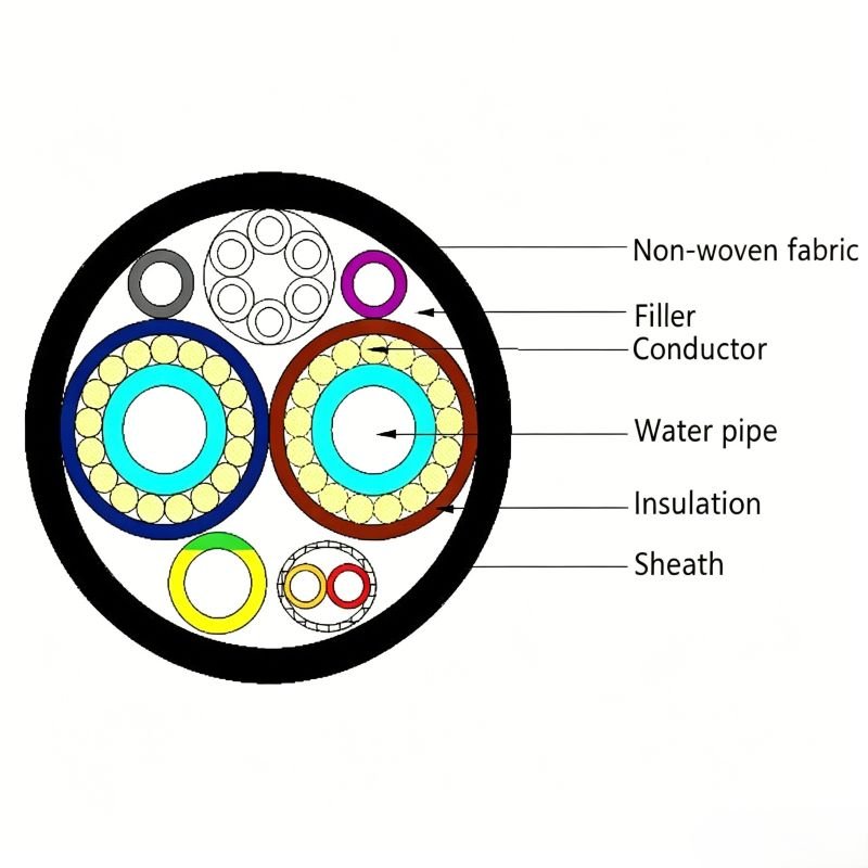
The cooling is what changes the construction. Instead of one heavy power conductor, a 600 A assembly uses a mixed build: a pair of 2 AWG (≈ 33.6 mm²) conductors forms the cooled current path, alongside an auxiliary power core, a shielded signal pair and control cores — a named peer configuration for 600 A NACS is 2 × 2 AWG (cooling) + 1 × 13 AWG + (2 × 18 AWG) P2 + 4 × 18 AWG. That works out to a current density of roughly 17.9 A/mm² in the cooled conductors, against the 4–6 A/mm² that conventional air-cooled design practice assumes. The consequence is a cable that a driver can still lift and bend while it carries three to four times the current that copper of that size would otherwise allow.
Electrically, the assembly sits inside three different regional frameworks and it is worth keeping them apart. The cable itself follows IEC TS 62893-4-2:2021, which sets a maximum conductor temperature of 90 °C and assumes the charging cable is used with Class II equipment. The DC coupler follows IEC 62196-3:2026, which is a dimensional compatibility standard — the rated voltage and current values themselves come from IEC 62196-1:2025. In North America the connector standard is UL 2251-2022, which raised the scope to 800 A / 1000 V AC / 1500 V DC and was the first edition to write active cooling and dynamic current control into the body of the standard; it also requires that a cooled product state a non-cooled current rating as well. In China the DC interface is GB/T 20234.3-2023, which lifted the earlier 250 A ceiling to 800 A / 800 kW and added active cooling and temperature monitoring. NACS is no longer a proprietary outline: it is published as the SAE J3400 series.
On temperature we are deliberately narrow. The cable rating is 90 °C conductor temperature, per the IEC specification. Silicone insulation has a higher intrinsic material capability, but in an assembly with a TPU outer jacket the continuous rating is set by the jacket, so we quote the cable rating and confirm the assembly figure for the selected variant rather than publishing a single wide range. On the contact side, UL 2251-2022 judges at a contact temperature of no more than 100 °C at maximum rated current, while the vendor convention for terminal temperature rise is < 50 K; the two are different measurements and we state both with their conditions rather than blending them.
Coolant specification — fluid type, flow rate and inlet temperature — is agreed per project with the charger manufacturer rather than fixed on the data sheet, because it is the charger, not the cable, that owns the cooling circuit. For the AC side of the same site see our Type 2 32A IEC 62196 EV Charging Cable, and for the supply side of the charger, our Cu/XLPE/SWA/PVC 0.6/1 kV Power Cable.
More about the manufacturer: About SORIVO →
The IEC part covering DC charging cables for mode 4 of IEC 61851-1 that are used with a thermal management system — the correct reference for a liquid-cooled cable, with a 90 °C conductor rating.
The coolant circuit is integrated with the conductor path rather than wrapped around a conventional core, which is how the assembly reaches 600 A at a manageable outer diameter.
600 kW of charging power at the rated point. Higher current and 1500 V DC variants follow the UL 2251-2022 and GB/T 20234.3-2023 envelopes and are quoted on request.
CCS1 and CCS2 DC couplers to the dimensional-compatibility standard, with the rated voltage and current values taken from IEC 62196-1:2025 as the standard requires.
DC power contact temperature sensing brought out to the charger, so the dispenser can run dynamic current control instead of a fixed current limit.
Covered up to 800 A and 1500 V DC. The 2022 edition also fixes the contact judgement at ≤ 100 °C at maximum rated current and expects a declared non-cooled current rating.
The Chinese DC interface as revised in 2023 — up to 800 A and 800 kW, with active cooling and temperature monitoring added to the requirements.
Cable, coolant path and coupler are supplied as one assembly, with dielectric, insulation-resistance and continuity checks recorded before shipment.
The applications below are the ones where 500 A class air-cooled cable stops being practical — either because of current, or because of the weight and stiffness that come with it.
600 kW-class charging plazas on long-distance routes, where each bay has to add range in the shortest possible stop.
Van, taxi and light-commercial depots running multiple high-power sessions per vehicle per day, where cable weight affects driver handling.
Multi-bay city hubs with liquid-cooled dispensers, where a thin, flexible cable also means a smaller cable management system.
Opportunity charging for heavy vehicles, where high current and short turnaround times come together.
Northern corridors and mountain routes, where a cable that stays flexible matters as much as the current it carries.
IP67 mated couplers and a sealed coolant circuit for installations exposed to salt air and heavy rain.
Replacing an air-cooled high-power cable assembly on an existing dispenser to raise the delivered current without changing the cabinet.
Volume supply to charger manufacturers who need the cable assembly as a released component with its own documentation set.
The complete parameter set — the same data our engineers quote from.
| Element | Conductor | Function | |
|---|---|---|---|
| Cooled current path | 2 × 2 AWG (≈ 2 × 33.6 mm²) | Carries the DC current and forms the liquid-cooled circuit | |
| Auxiliary power core | 1 × 13 AWG (≈ 2.6 mm²) | Auxiliary supply within the assembly | |
| Shielded signal pair | (2 × 18 AWG) P2 | Data / communication pair with shield | |
| Control and signal cores | 4 × 18 AWG (≈ 0.75 mm²) | Control, proximity and sensing conductors |
The configuration above is the published construction of a named peer 600 A liquid-cooled assembly, used here because it is the clearest available illustration of how a cooled DC cable is actually built — it is not a measurement of our own product. The exact construction of the assembly we quote is confirmed against the selected variant and the charger-side interface before the order is released. Current density in the cooled conductors is approximately 17.9 A/mm² at 600 A, against 4–6 A/mm² assumed in conventional air-cooled design practice.
| General Information | |
| Product Name | Liquid-Cooled Ultra-Fast EV Charging Cable 600A DC 1000V |
| Product Type | Liquid-cooled DC charging cable assembly with integrated coolant circuit |
| Cable Standard | Designed to IEC TS 62893-4-2:2021 — charging cables for electric vehicles up to 0.6/1 kV, Part 4-2: DC charging cables intended to be used with a thermal management system |
| Comparison Reference | IEC 62893-4-1:2020 — the same DC charging application without a thermal management system |
| Coupler Standards | IEC 62196-3:2026 (dimensional compatibility) with ratings to IEC 62196-1:2025; UL 2251-2022 (North America); GB/T 20234.3-2023 (China); SAE J3400 series for NACS |
| Equipment Class | Class II equipment, as assumed for charging cables specified in the IEC 62893 series |
| Cooling Method | Direct liquid cooling with an integrated coolant channel and circulation circuit |
| Coolant Specification | Agreed per project with the charger manufacturer — fluid type, flow rate and inlet temperature are properties of the charging system, not fixed on this data sheet |
| Electrical Ratings | |
| Rated Current (DC) | 600 A continuous |
| Current Steps | 250 A / 300 A / 350 A / 600 A classes are the common liquid-cooled tiers; the 600 A class is the rating of this page |
| Non-Cooled Rating | Declared separately, as UL 2251-2022 requires for actively cooled equipment — confirmed for the selected assembly |
| Rated Voltage (DC) | 1000 V DC; 1500 V DC available on request, within the UL 2251-2022 envelope |
| Max. Charging Power | 600 kW at 600 A × 1000 V DC; 800 kW class available on request |
| Insulation Resistance | ≥ 2000 MΩ at DC 1000 V |
| Withstand Voltage | 3200 V AC |
| Contact Resistance | ≤ 0.5 mΩ |
| Contact Temperature | ≤ 100 °C at maximum rated current (UL 2251-2022 judgement) |
| Terminal Temperature Rise | < 50 K at rated current, at the test ambient temperature declared by the manufacturer |
| Temperature Monitoring | DC power contact temperature monitoring with sensing leads brought out for dynamic current control |
| Dynamic Current Control | Supported, per the temperature feedback path required by UL 2251-2022 |
| Construction | |
| Conductor Material | Flexible annealed copper; silver-plated copper available |
| Cooled Conductor | 2 AWG class (≈ 33.6 mm² per conductor) in the named peer 600 A construction |
| Current Density | ≈ 17.9 A/mm² in the cooled conductors at 600 A |
| Control and Signal Cores | Shielded signal pair plus control cores in the 18 AWG class, in the named peer construction |
| Insulation | Silicone — selected for the temperature and dielectric requirements of a liquid-cooled assembly |
| Outer Sheath | TPU — oil-resistant and abrasion-resistant; the continuous rating of the finished assembly is limited by the jacket |
| Cable OD | Confirmed against the selected assembly; a 600 A cooled construction stays well below the diameter of an air-cooled equivalent |
| Coupler Housing | Thermoplastic, UL 94 V-0; UL 2251-2022 additionally requires a flammability rating of at least HB and a thermal index of at least 100 °C |
| Contact Plating | Copper alloy with silver plating; UL 2251-2022 recommends a silver or silver-alloy layer of at least 5 µm |
| Mechanical and Environmental | |
| Cable Conductor Temperature | +90 °C maximum, per IEC TS 62893-4-2:2021 |
| Insulation Material Capability | Silicone insulation has a higher intrinsic temperature capability than the cable rating; it is the jacket that limits the finished assembly |
| Connector Ambient Range | −30 °C to +50 °C |
| Component Thermal Cycling | −40 °C to +125 °C over 10 cycles, per UL 2251-2022, with a temperature-rise variation within ±5 °C |
| Ingress Protection | IP67 mated at the coupler / IP55 at the charger-side back housing |
| Mechanical Life | > 10,000 no-load mating cycles |
| Flame Performance | UL 94 V-0 on plastics; IEC 60332-1-2 vertical flame propagation, which is the test method referenced by IEC TS 62893-4-2:2021 |
| Coolant Circuit | Sealed, with leak testing recorded for the assembly before shipment |
| Configuration & Logistics | |
| Cable Length | 3 m / 5 m / 7 m standard; other lengths to order |
| Coupler Options | CCS1, CCS2, GB/T (20234.3-2023), CHAdeMO, NACS (SAE J3400 series) |
| Housing and Colour | Standard black; housing colour and branding to order |
| Packaging | Individual carton with foam protection; custom packaging per request |
| MOQ | 100 units; sample orders negotiable |
| Lead Time | 15–25 working days; stocked configurations may be available sooner |
| Customization | Cable length, coupler type, housing colour, logo and packaging |
Final selection depends on the charger’s cooling circuit, the delivered current profile, the ambient conditions at the site and the regional coupler standard. The coolant specification and the non-cooled current rating are agreed with the charger manufacturer against the selected assembly, and our engineers confirm the construction and documentation scope for your project before release. Certification scope should always be confirmed against the certificate for the selected configuration.
The IEC technical specification for DC charging cables used with a thermal management system. It is a Technical Specification, so we describe the assembly as designed to it rather than certified to it, and we state its 90 °C conductor rating.
Request document set →The DC and AC/DC coupler dimensional-compatibility standard and the general standard that carries the rated voltage and current values. Coupler test documentation is provided with the quotation.
Request test report →The North American coupler safety standard covering active cooling and dynamic current control, and the Chinese DC interface standard as revised in 2023. Scope and edition are confirmed per configuration.
Request certificate copy →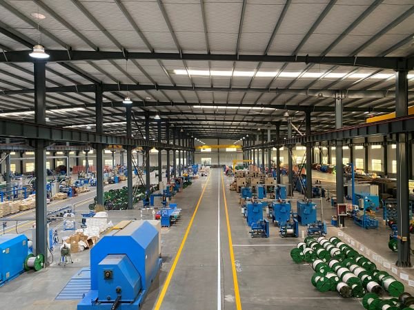
Every liquid-cooled assembly is built to order, so the release checks happen on the finished cable rather than on the drum alone.
Tell us the charger model, the coupler standard and the delivered current you need.
We confirm connector variants, cable construction and quotation within one working day.
Sample for qualification — stocked configurations within a few working days.
15–25 working days with assembly-level test documentation.
Carton packing, shipping documents and support through charger integration and field commissioning.
Tell us the coupler standard, cable length and delivered current — we reply within one working day.
The more detail you give, the faster and more accurate our quotation. Our engineers reply within one working day.
Thanks — our engineers will reply within one working day.