Professional cable manufacturer

Professional cable manufacturer
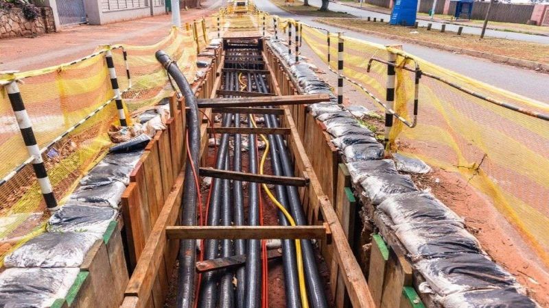
A few years back, I got a call from a project manager on a solar farm in Spain. They'd buried 95 mm² XLPE/SWA/PVC cables at 1.2 m depth, spaced 200 mm apart — textbook layout. The design load was 220 A per circuit. Two months after commissioning, the cable surface temperature at one section hit 85°C. The conductor inside was pushing well past the 90°C limit.
Everyone checked the usual suspects. Load imbalance? No. Ambient spike? Unlikely at 1.2 m. Voltage drop? Within spec. Then someone tested the soil. The backfill was dry sand with a thermal resistivity of ρ = 2.8 K·m/W. The design had assumed ρ = 1.0 — standard reference condition. That one number was the difference between a working installation and a 40 km cable replacement.
Soil thermal resistivity is probably the single most underappreciated variable in underground cable design. This guide explains what it is, how to measure it, and — most importantly — how to avoid learning about it the hard way.
Soil thermal resistivity (ρ, measured in K·m/W) tells you how well the ground conducts heat away from a cable. A low value means the soil is a good conductor of heat; a high value means it's a poor one — like an insulating blanket around the cable.
In IEC 60287, the external thermal resistance (T4) is one of the four components that determine a cable's total ampacity. The ρ value feeds directly into T4. Double the soil thermal resistivity, and the ampacity of a buried cable can drop by 18–30% — even though the cable itself hasn't changed at all.
Here's where things vary wildly. The reference condition assumed by BS 7671 (and IEC 60364-5-52) ampacity tables is ρ = 1.0 K·m/W — roughly moist clay. Note that IEC 60287-3-1 gives a reference range of 0.7–1.2 K·m/W, and recommends ρ = 2.5 K·m/W as the conservative design value when no site data is available. Real-world soils span a much wider range than any single reference value.
| Soil Type | Moisture Condition | ρ (K·m/W) | Heat Dissipation |
|---|---|---|---|
| Wet clay / silt | Saturated | 0.5–0.7 | Excellent — better than standard reference |
| Moist clay / loam | Damp | 0.7–1.0 | Good — standard reference range |
| Wet sand | Moist | 1.0–1.5 | Moderate — some derating needed |
| Gravel / crushed stone | Dry | 1.5–2.5 | Poor — significant derating |
| Dry sand | Dry | 2.0–3.0 | Very poor — expect 18–27% ampacity reduction |
| Rock / granite | Dry | 2.0–3.5 | Very poor — avoid direct burial if possible |
| Thermal backfill (engineered) | Compacted | 0.5–0.8 | Excellent — matches or beats wet clay |
The spread is enormous. A cable buried in wet clay at ρ = 0.6 can carry over 45% more current than the same cable in dry sand at ρ = 2.5. That's not a safety margin — that's the difference between a cable that runs cool and one that cooks itself.
Let's be concrete. Take the same cable from the installation-method comparison — 4-core 120 mm² Cu/XLPE/SWA/PVC, 0.6/1 kV, 90°C conductor rating — buried at 1 m depth. All variables fixed except soil type.
| Soil Condition | ρ (K·m/W) | Ampacity (A) | vs. ρ = 1.0 | Design Implication |
|---|---|---|---|---|
| Wet clay (saturated) | 0.6 | 205 A | +14% | Can safely load higher than table value |
| Moist clay (reference) | 1.0 | 180 A | — (baseline) | Standard BS 7671 / IEC design condition |
| Wet sand | 1.5 | 160 A | –11% | Minor derating — usually still OK |
| Dry sand / gravel | 2.0 | 148 A | –18% | Consider upsizing cable or using backfill |
| Dry sand (hot climate) | 2.5 | 140 A | –22% | Must upsize or use thermal backfill |
| Very dry / rocky | 3.0 | 132 A | –27% | Avoid direct burial — use ductbank or route change |
This is the part that catches even experienced engineers off guard. When a loaded cable heats the surrounding soil beyond a certain threshold — typically 50–60°C at the cable surface — moisture begins to migrate away from the heat source, drying out the soil immediately around the cable. The result is a two-layer soil profile: a dry, high-resistivity zone (ρ = 2.0–3.0) directly adjacent to the cable, surrounded by undisturbed moist soil (ρ = 1.0 or lower).
This is known as the critical temperature mechanism. Once the cable surface exceeds the critical temperature (roughly 55–65°C for most soils, depending on particle size and mineral composition), the moisture migration creates a self-reinforcing cycle: drier soil → higher ρ → less heat dissipation → higher cable temperature → more drying. In field measurements, I've seen this push the effective ρ from an initial 1.0 to 2.5 or more within weeks of operation at high load.
The effect is most pronounced in fine-grained soils (silt, clay, loam) starting at moderate moisture levels. Coarse soils like clean sand tend to drain naturally and show less dramatic moisture migration, but their baseline ρ is already higher. This is why lab-tested soil samples at the design stage can give misleadingly optimistic results — a sample taken in spring (high moisture) and tested at room temperature will show ρ = 0.8–1.0, but the same soil around a loaded cable in late summer may exhibit an effective ρ of 2.0–2.5 across the dry zone.
There are two widely accepted test methods for determining soil thermal resistivity on site:
| Method | Standard | How It Works | Best For |
|---|---|---|---|
| Thermal needle probe | IEEE 442-2017 | A heated needle is inserted into the soil; the temperature rise over time gives ρ (both IEEE 442 and ASTM D5334 use the same transient heat method — the difference is field vs. lab application) | On-site, in-situ testing before trenching |
| Transient hot wire | ASTM D5334 | A wire embedded in a soil sample is heated; thermal conductivity is derived from the temperature transient. Same transient heat principle as IEEE 442 | Lab testing of soil samples from boreholes |
For most projects, I recommend IEEE 442 field testing at multiple points along the cable route — especially if the soil type varies. A single sample from one borehole can miss a dry pocket 50 m down the trench. Test at least three locations per kilometre of route, and test at the actual cable depth.
If the soil on your site isn't ideal, you have options. Here's how I weigh them:
When: ρ ≤ 1.5, or load is well below cable capacity
Cost: $0
Risk: Low if load margin exists; moderate if moisture migration is possible
✅ Simple, no extra work ❌ Wastes cable capacity
When: ρ = 1.5–2.5, especially in hot/dry climates
Cost: Low–moderate ($15–30/m trench)
Materials: Sand-cement mix, fluidised thermal backfill (FTB), or selected local soil
✅ Best value fix ❌ Needs quality control during placement
When: ρ = 2.0–3.0, short route, or backfill not feasible
Cost: Moderate–high (cable cost + larger trench)
Rule: One cross-section up ≈ 15–20% ampacity gain
✅ Simple, no extra installation steps ❌ More copper cost
When: ρ > 2.5, or rocky terrain makes direct burial impractical
Cost: High (concrete duct + pulling)
Benefit: Stable thermal environment, replaceable cables
✅ Most reliable long-term ❌ Highest upfront cost
Not sure what soil conditions you're dealing with — or which cable size keeps you safe in the ground you've got? Sorivo's engineers work with IEC 60287, BS 7671, and NEC ampacity calculations every day. Email us at sale@sorivocable.com with your project parameters and we'll run the numbers for free.