Professional cable manufacturer

Professional cable manufacturer
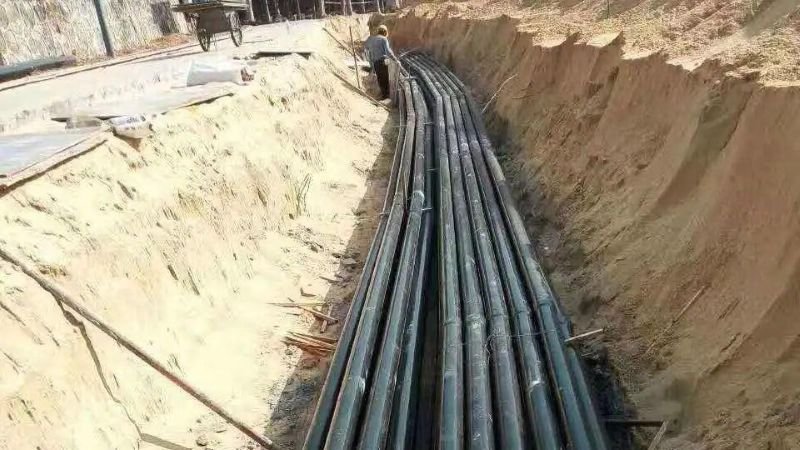
Here's something I've noticed after years of reviewing cable specs for projects across different continents: most engineers spend hours selecting the right conductor size and insulation type, then casually toss "direct burial, standard conditions" into the spec and call it done.
The thing is, "standard conditions" don't exist once you leave the textbook. A cable that lasts 30 years in free-draining sandy soil might fail in a decade when buried in heavy clay. The same XLPE/SWA/PVC cable that performs beautifully in the Arabian desert can suffer premature sheath degradation in the waterlogged ground of Southeast Asia. The difference isn't the cable itself — it's what the soil does to it.
Soil conditions affect three things that determine your cable's real-world performance and lifespan:
Ignore any of these, and you're gambling with the installation's design life. Get them right, and your buried cable will outperform its datasheet expectations.
This guide walks through each common soil condition — what happens underground, how it affects cable performance, and exactly what to spec for 0.6/1kV LV power cables (with principles that extend to medium voltage 11kV and 33kV installations). I've included real ampacity derating figures, installation details that actually matter on site, and the standards you need to reference.
Before we get into individual soil types, you need to understand the single most important soil property for cable sizing: thermal resistivity (ρ₄). It's measured in K·m/W, and it tells you how easily heat moves through the soil around your cable.
Per IEC 60287, the external thermal resistance (T₄) is often the dominant term in the cable rating equation — it can account for over 70% of the total temperature rise in a buried cable. Get this wrong, and your ampacity calculation is essentially fiction.
The key takeaway: T₄ is directly proportional to ρ₄. Double the soil thermal resistivity, and you roughly halve the cable's current-carrying capacity — all else being equal. Note that the full IEC 60287 calculation result (I) relates to T₄ by a square root, so the relationship between ρ₄ and ampacity is approximately inverse-square-root — the "halve the capacity" claim is a practical simplification for typical cable geometries and burial depths.
The table below draws from IEC 60287-3-1, CIGRE TB 714, and IEEE 442. These are the numbers I use when reviewing cable specs for buried installations.
| Soil Condition | Moist / Wet (K·m/W) | Dry (K·m/W) | IEC 60287 Default |
|---|---|---|---|
| Sand (free-draining) | 0.7 – 1.0 | 1.5 – 2.5 | 1.0 |
| Sandy loam | 0.7 – 1.2 | 1.5 – 2.5 | 1.0 |
| Clay (heavy / poorly drained) | 0.9 – 1.2 | 2.0 – 3.0 | 1.2 |
| Silt / silty clay | 0.6 – 1.0 | 2.0 – 2.5 | 1.0 |
| Rock / stone backfill | 1.0 – 1.5 | 2.0 – 3.0 | 1.5 |
| Peat / organic soil | 0.5 – 0.7 | 1.0 – 1.5 | 0.7 |
| Engineered backfill (sand-cement) | 0.5 – 0.7 | 0.8 – 1.2 | — |
Now let's get into the practical stuff — what cable to choose for each common soil condition, and why. I've organised this by soil type so you can jump straight to what matches your project site.
What happens underground: Sandy soil drains freely and doesn't hold moisture against the cable surface. Thermal resistivity is moderate (0.7–1.0 K·m/W when moist) but can rise significantly when dry. The main risk is that sand shifts easily — backfill settlement can create voids that reduce heat transfer.
Recommended cable: Standard BS 5467 or BS 6724 — XLPE insulated, SWA armoured, PVC or LSZH sheathed. This is the least demanding soil condition for buried cable.
Key considerations:
Design life: 25+ years with standard SWA construction.
Standards: BS 5467, IEC 60502-1, BS 7671 Table 4D4A
What happens underground: Sharp rocks can puncture or abrade the cable sheath during installation and throughout the cable's life as the ground settles. Point loading from irregular stones creates localised stress on the armour. Thermal resistivity of rock backfill is higher than sand or soil, which reduces ampacity.
Recommended cable: BS 5467 XLPE/SWA/PVC or BS 6724 XLPE/SWA/LSZH — but with enhanced sand bedding. I'd also consider upgrading to an HDPE outer sheath in particularly sharp ground conditions.
Key considerations:
Design life: 25+ years with proper sand bedding and appropriate armour.
Standards: BS 5467, IEC 60502-1, NJUG Guidelines (UK) for trench specification
What happens underground: Clay holds water — which sounds like it would be good for thermal performance — but it also expands and contracts with moisture changes, creating mechanical stress on the cable. When clay dries out (and it will, around a loaded cable), it shrinks and cracks, forming air gaps that dramatically increase thermal resistivity. The wet-to-dry swing in clay can push ρ₄ from 1.0 to 3.0 K·m/W.
Recommended cable: BS 5467 or BS 6724 XLPE/SWA — with separate CPC (circuit protective conductor). In permanently wet clay, consider upgrading to an MDPE-sheathed or LSZH-sheathed cable for better moisture resistance.
Key considerations:
What happens underground: The cable is effectively sitting in water permanently. While water is excellent for thermal dissipation (low ρ₄ ≈ 0.7 K·m/W), prolonged immersion creates two serious problems: moisture ingress through the sheath over time, and accelerated corrosion of metallic armour components. Standard PVC sheaths are not designed for permanent submersion — they absorb moisture slowly, and over 10–15 years, water can reach the armour and conductor.
Recommended cable: For waterlogged conditions, standard SWA cables are not sufficient. You need an AD8-rated cable (continuous submersion per IEC 60529) with a transversely watertight construction. Options include:
Key considerations:
What happens underground: Industrial sites, landfills, and coastal areas expose buried cables to chlorides, sulphates, acidic groundwater, and other corrosive agents. PVC sheaths can degrade in certain chemical environments. Standard galvanised steel wire armour may corrode faster than the cable's design life expects.
Recommended cable: BS 6724 XLPE/SWA/LSZH with tinned copper conductors — look for TÜV or BASEC certified products with documented chemical resistance test results. In severe environments, consider upgrading to:
Key considerations:
Here's a quick-reference table for how each soil condition affects ampacity. These factors apply to the base IEC 60364-5-52 rating (ρ₄ = 1.0 K·m/W, 20°C ambient, 0.8 m depth).
| Soil Condition | Assumed ρ₄ (K·m/W) | Derating Factor (vs. Base Rating) | Notes |
|---|---|---|---|
| Very moist sand / loam | 0.7 | 1.05–1.10 | Cooler running than reference |
| Standard reference (dry sand) | 1.0 | 1.00 | IEC 60287 default |
| Heavy clay (moist) | 1.2 | 0.90–0.95 | Reduced by 5–10% |
| Heavy clay (dry / cracked) | 2.0–2.5 | 0.75–0.85 | Serious derating required |
| Rock backfill | 1.5 | 0.88–0.93 | ~10% reduction typical |
| Waterlogged (if cable rated) | 0.7 | 1.05–1.10 | Better cooling, but cable must be AD8 rated |
| Dry sand (desert conditions) | 2.5–3.0 | 0.65–0.75 | Major derating — use engineered backfill |
The table below summarises the key installation parameters that vary by soil condition. Depth, bedding, and backfill all need to be adjusted based on what you're digging into.
| Parameter | Sandy | Rocky | Clay | Waterlogged |
|---|---|---|---|---|
| Min. burial depth (LV) | 600 mm (450 mm only with additional mechanical protection) | 600 mm | 600 mm | 600–750 mm |
| Sand bedding below | 75 mm | 100–150 mm | 100 mm | 100 mm |
| Sand bedding above | 75 mm | 100–150 mm | 100 mm | 100 mm |
| Backfill material | Excavated sand | Imported granular | Imported granular (not clay) | Granular or engineered |
| Warning tape | Standard | Standard | Standard | Standard |
| Protective tiles / slab | Optional | Recommended | Optional | Recommended |
| Separate CPC | Optional | Not required | Recommended | Mandatory |
| Duct recommendation | Optional | Not required | Optional | Recommended |
For a complete breakdown of cable laying methods including trench cross-sections, see our Cable Laying Methods Guide.
Here's the thing about buried cables — you can't see them after installation. The quality difference between an economy cable and a properly manufactured one doesn't show up on day one. It shows up in year 12 when the economy cable's PVC sheath has embrittled from soil chemicals and water ingress has started corroding the armour.
| Property | Economy / Generic Grade | Sorivo Premium Grade |
|---|---|---|
| Conductor | Bare copper (class 2, may under-size by ~3–5%) | Tinned or bare copper per IEC 60228, full cross-section guaranteed |
| Insulation | PVC (70°C rated, may use recycled compound) | XLPE (90°C rated, virgin compound, consistent wall thickness) |
| Armour | Thinner gauge galvanised steel, uneven winding | Full-gauge galvanised steel wires, uniform lay angle per BS 5467 / IEC 60502-1 |
| Outer sheath | PVC, basic formulation, inconsistent thickness | PVC, LSZH, or MDPE — uniform wall, 2.60% ± 0.25% carbon black per GB/T 15065 for UV resistance |
| Water blocking | None | Optional water-blocking tapes and swellable powders for waterlogged applications |
| Traceability | No metre marking or batch number | Metre-marked every metre, batch-traceable to production date |
| Certification | Self-declared (may print fake standard numbers) | Third-party tested — BS 5467, BS 6724, IEC 60502-1 |
| Warranty | 1–5 years | 25-year design life with full material traceability |
For more on how to verify cable quality before buying — including simple field checks — see our TÜV/UL Verification Guide and Cable Testing Standards Guide.
Use this matrix to quickly match your site conditions to the right cable spec:
| Soil Condition | Cable Standard | Armour | Sheath | Conductor | Special Requirements |
|---|---|---|---|---|---|
| Free-draining sand | BS 5467 | SWA | PVC | Copper (bare) | Standard sand bedding |
| Rocky ground | BS 5467 | SWA | PVC or HDPE | Copper (bare) | Enhanced sand bedding 150 mm each side |
| Heavy clay | BS 5467 / BS 6724 | SWA | PVC or LSZH | Copper (bare) | Separate CPC; imported backfill |
| Waterlogged | BS 6724 or AD8 rated | SWA | LSZH, MDPE, or HDPE | Copper (tinned) | AD8 rating required; separate CPC mandatory |
| Chemical / coastal | BS 6724 | AWA or SWA | LSZH or HDPE | Copper (tinned) | Site soil analysis; AWA preferred for severe environments |
| Mixed / unknown | BS 6724 | SWA | LSZH | Copper (tinned) | LSZH covers more conditions; tinned copper for corrosion margin |
Let's put some numbers on this. The table below compares three scenarios for a 100-metre LV feeder run in heavy clay soil, using the same conductor size (95 mm² XLPE) but different approaches to the soil-specific risks.
Assumptions: 95 mm² XLPE/SWA cable prices based on 2026 reference pricing for Southeast Asia. Installation labour estimated at 40% of material cost. Energy loss calculated at $0.12/kWh with 60% load factor. Replacement cost includes full re-excavation, cable removal, new cable supply, and reinstallation. All figures are indicative — actual costs vary by region, site accessibility, and market conditions.
| Scenario | Initial Cost (cable + install) | Year 0–10 | Year 10–25 | 25-Year Total |
|---|---|---|---|---|
| Economy cable, no derating applied | $3,200 | Annual 2.5% energy loss from overheating ($480/yr) | Sheath cracking, armour corrosion — replacement needed by year 14 | $18,500+ |
| Standard BS 5467 SWA, correct derating | $4,100 | Normal operation | Minor sheath degradation, reduced ampacity margin | $8,200 |
| BS 6724 SWA/LSZH + separate CPC + engineered backfill | $5,800 | Normal operation, full capacity | Full performance maintained, 25-year design life | $7,100 |
The premium option costs 80% more upfront but saves over $11,000 across 25 years. That's the hidden cost of ignoring soil conditions — you don't see it at purchase, but you'll feel it when the cable fails a decade early.
For a more detailed breakdown of cable lifecycle costs, see our Cable TCO Guide.

Honestly? I wouldn't. Standard SWA cables with PVC sheaths are designed for free-draining soils. In permanently waterlogged conditions, the PVC sheath will absorb moisture over time, eventually reaching the steel wire armour and accelerating corrosion. Most major cable manufacturers explicitly state that their standard armoured cables are not recommended for permanently wet ground.
If you're in waterlogged ground, specify an AD8-rated cable with a transversely watertight construction and a separate CPC. The upfront cost is higher, but you avoid an expensive dig-up and replacement in year 12–15.
Yes — and I'd argue it's more important with SWA than without. Here's why: SWA protects against general mechanical stress, but it doesn't eliminate point loading from sharp rocks. A single stone pressing against the cable at the bottom of a trench can create a localised deformation in the armour that compromises its integrity over time.
The sand envelope distributes those point loads across a wider area. Minimum 100 mm below and 100 mm above the cable in standard rocky ground; increase to 150 mm if the rocks are particularly sharp or the backfill is coarse. The cost of an extra 50 mm of sand on each side is negligible compared to the excavation cost if the cable gets damaged.
Start with the base ampacity from the manufacturer's datasheet (typically at ρ₄ = 1.0 K·m/W). For heavy clay in moist condition, assume ρ₄ ≈ 1.2 K·m/W and apply a derating of ~0.90–0.95. But here's the trick — clay dries out around a loaded cable, and the dry zone can push ρ₄ to 2.0–3.0. I usually design for the dry case and use the factor 0.75–0.85.
The full IEC 60287 formula is the most accurate method, but for a quick check: if your clay site has visible cracks in the dry season, use the derating for dry conditions. If it stays consistently moist year-round, use the moist value. And if you're unsure, install a sand-cement engineered backfill — it eliminates the variable entirely.
For more on derating factors with worked examples, see our Cable Ampacity Derating Guide.
Not automatically. Standard H1Z2Z2-K per EN 50618 is not inherently AD8 rated — the standard doesn't require it. However, some manufacturers produce H1Z2Z2-K variants with AD8 construction (e.g., Lapp's ÖLFLEX SOLAR XLWP or KUKA's AD8 solar cable), which include transversely watertight layers and are certified for continuous submersion.
If you're burying solar DC cables in waterlogged soil or a high water table area, don't assume standard H1Z2Z2-K will do the job. Look for the specific AD8 marking on the datasheet and certificate. For standard dry-soil solar farm burial, regular H1Z2Z2-K in conduit is perfectly adequate — see our Solar Cable Burial & Conduit Guide.
Fair question. Sand bedding is simply clean, stone-free sand placed around the cable — it provides mechanical cushioning and a consistent thermal medium. Engineered backfill is a specifically formulated mixture (typically sand + cement or sand + bentonite in controlled proportions) designed to maintain stable thermal resistivity even when the surrounding soil dries out.
You need engineered backfill when:
For most LV direct burial in residential or commercial projects, standard sand bedding is sufficient. Engineered backfill is typically specified for MV/HV cables and critical infrastructure feeders.
Here's the short version of everything above, in the order I recommend you apply it:
Getting these five steps right costs a little more upfront. But as the TCO comparison in Section 8 shows, it saves far more than it costs over 25 years.
Our technical team can review your site conditions and recommend the right cable construction, ampacity rating, and installation method — whether it's rocky mountain terrain, coastal clay, or waterlogged paddy field.
Get a Free Cable Sizing ProposalStandards referenced in this guide: IEC 60287-1-1:2023, IEC 60287-3-1:2017, IEC 60364-5-52:2024, BS 7671:2018+A2:2022, BS 5467, BS 6724, IEC 60502-1, IEC 60529, EN 50618, HD 60364-5-51, CIGRE TB 714, IEEE 442.
Disclaimer: Ampacity derating factors are indicative and based on standard reference conditions. Always verify with the cable manufacturer's certified data for your specific cable construction, installation depth, and site conditions.