Professional cable manufacturer

Professional cable manufacturer
Home » Products » Control & Instrumentation » Coaxial Cable — RG6 / RG11 (75 Ω) & RG58 / RG213 (50 Ω) RF Cable
Two separate impedance families on one datasheet-driven page: 75 Ω CATV & satellite coax (RG6, RG6 Quad Shield, RG11) and 50 Ω RF & test coax (RG58, RG213) — construction and attenuation quoted per model, never combined.
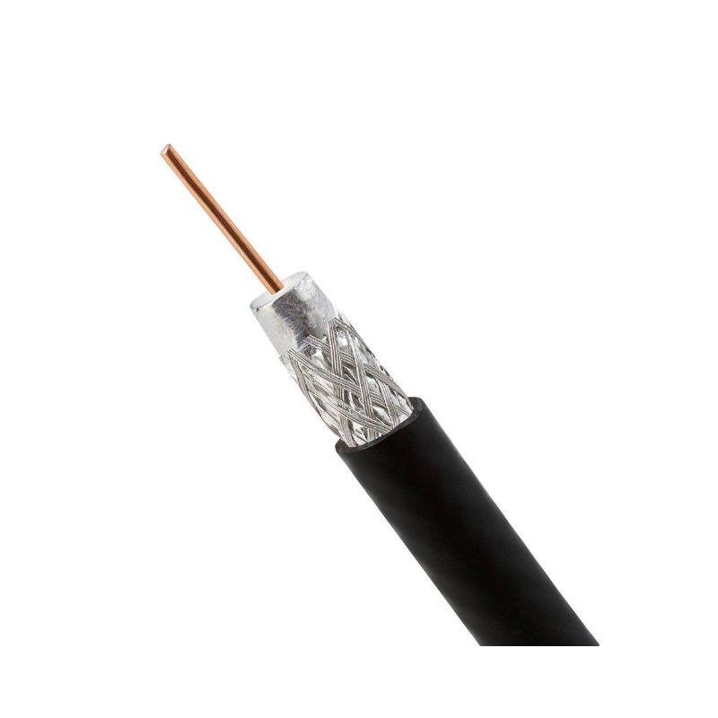
What a buyer fixes before a coaxial quotation can be priced — which impedance family, which model, which inner conductor material and which jacket.
This page covers flexible coaxial cable in the two impedance families that dominate RF work: the 75 Ω family (RG6, RG6 Quad Shield and RG11) used for CATV, satellite and video distribution, and the 50 Ω family (RG58 and RG213) used for RF test, antenna feeders and instrumentation. Each model is quoted from its own construction: inner conductor, dielectric, shield layers, jacket and attenuation.
The two families are not interchangeable. Impedance is fixed by the conductor and dielectric geometry, not by the connector: a 75 Ω cable terminated with a 50 Ω connector, or the reverse, produces a mismatch and reflections at the joint. Selecting one family to save time on the other is the most common and most expensive mistake on a coax order, so the specifications below are kept strictly separate — 75 Ω in Tables 1 and 2, 50 Ω in Tables 3 and 4.
Inside a family the inner conductor material decides the loss, and it has to be written at material level, not as "copper". The RG6 and RG11 constructions here use CCS (copper-clad steel) — RG6 at Φ 1.02 mm and RG11 at 1.63 mm — while RG58 uses tinned copper and RG213 uses bare copper (BC). The published DC resistance of the inner conductor shows the difference plainly: 21.7 Ω/km for RG6 CCS against 6.0 Ω/km for RG213 bare copper. A customer comparing only the outer diameter will read that difference out of the attenuation column instead.
Shield layer count is a construction statement, not a rating. Standard RG6 here is a two-layer shield — one aluminium/polyester foil plus one aluminium braid — while RG6 Quad Shield is foil + braid + foil + braid, four layers, each with its own coverage figure. Table 1 lists all four layers individually with their coverage. Coverage is never summed: the layers shield differently and the individual figures are what the construction states.
Before the order is released, three things get fixed in writing: the model and impedance family, the inner conductor material (CCS as standard on RG6/RG11 — a bare copper version would be a separate ordered item), and the jacket compound and length. Values on this page are the published construction and attenuation data for the referenced models; the drawing, sample and incoming inspection of the delivered reels govern.
More about the manufacturer: About SORIVO →
75 Ω (RG6 / RG6 Quad Shield / RG11) and 50 Ω (RG58 / RG213) are specified, tabulated and priced separately — never on one row.
Copper-clad steel inner conductor, Φ 4.57 mm foam PE dielectric, 75 ± 5 Ω, jacket to Φ 6.91 mm in PVC or LSZH.
CCS 1.63 mm inner conductor with Φ 7.2 mm LDPE dielectric and Φ 10.3 mm jacket; 14.3 dB/100 m @ 1000 MHz.
Foil ≥ 25% + braid 80 × 0.12 mm ≥ 60% + foil ≥ 25% + braid 64 × 0.12 mm ≥ 40% — four layers, each stated on its own.
M17/155 = RG 58 C/U. Tinned copper 19 × 0.18 mm inner conductor, tinned copper braid 112 × 0.13 mm at 95% coverage.
M17/74 = RG 213/U. Bare copper 7 × 0.75 mm inner conductor at 6.0 Ω/km, bare copper braid 192 × 0.18 mm at 97% coverage.
Every figure is stated as dB/100 m at a named frequency. No attenuation value is ever quoted without its @ xxx MHz condition.
Values below are the published construction and attenuation data for the referenced models; the drawing, sample and incoming inspection govern.
Distribution, video, RF test and antenna work — matched to the impedance family the system actually needs.
75 Ω RG6 and RG11 drop and distribution runs for cable TV, broadband and MATV head-end systems.
75 Ω RG6 and RG6 Quad Shield runs between dish, multiswitch and receiver where shield integrity matters.
75 Ω RG6 and RG11 for analogue and HD video backbones, camera drops and video distribution panels.
50 Ω RG58 and RG213 patch and instrument leads in benches, calibration racks and EMC test setups.
50 Ω RG58 for short jumpers and RG213 for longer low-loss antenna feeders on radio and two-way systems.
75 Ω coax for studio routing, SDI-style video distribution and AV racks where impedance must stay 75 Ω.
Flexible 50 Ω and 75 Ω coax for marine radio, vehicle antenna feeds and mobile RF installations.
75 Ω riser and backbone coax for structured building distribution alongside the data cabling.
Four tables, deliberately split by impedance family: 75 Ω construction and attenuation first, then the 50 Ω family. No parameter line is shared between the two.
| 75 Ω — General | |
| Impedance Family | 75 Ω nominal — RG6, RG6 Quad Shield and RG11. Characteristic impedance tolerance is stated per model below as published for that construction |
| Characteristic Impedance | 75 ± 5 Ω per model as published for the referenced construction (RG6, RG6 Quad Shield, RG11) |
| Standards Framework | IEC 61196-1 (coaxial communication cables — generic specification) with the applicable sectional specification; ANSI/SCTE 74 for braided 75 Ω flexible RF drop cable in North America. MIL-C-17F 75 Ω outline numbers exist for these models (M17/2 = RG 6, M17/6 = RG 11); these are the standards the models belong to, not a certification claim for this page |
| Applications | CATV, satellite / DTH, MATV, CCTV and video distribution |
| 75 Ω — RG6 (single shield) | |
| Inner Conductor | CCS (copper-clad steel), Φ 1.02 mm |
| Dielectric | Foam PE, Φ 4.57 ± 0.20 mm |
| Shield 1 (inner) | Aluminium / polyester composite tape (Al/PET, bonded) — 100% coverage |
| Shield 2 (outer) | Aluminium braid 96 × 0.12 mm — 82% coverage |
| Outer Jacket | PVC or LSZH, Φ 6.91 mm |
| Nominal Capacitance | 54 pF/m |
| Velocity of Propagation | 83% |
| Insulation Resistance | > 5000 MΩ·km |
| Inner Conductor DC Resistance | 21.7 Ω/km |
| Outer Conductor DC Resistance | 24.1 Ω/km |
| Operating Temperature | −30 °C to +70 °C |
| Reference Weight | 45 kg/km |
| 75 Ω — RG6 Quad Shield (four shield layers) | |
| Inner Conductor | CCS (copper-clad steel), Φ 1.02 mm |
| Dielectric | Foam PE, Φ 4.60 ± 0.20 mm |
| Quad Shield Explained | Foil + braid + foil + braid = four shield layers, against two layers (one foil + one braid) on standard RG6. Shield layers are bonded at both ends for a coaxial screen to work |
| Shield 1 | Aluminium / polyester (Al-mylar) tape — ≥ 25% |
| Shield 2 | Aluminium braid 80 × 0.12 mm — ≥ 60% |
| Shield 3 | Aluminium / polyester (Al-mylar) tape — ≥ 25% |
| Shield 4 | Aluminium braid 64 × 0.12 mm — ≥ 40% |
| Outer Jacket | PVC or LSZH, Φ 7.55 ± 0.20 mm |
| Nominal Capacitance | 54 pF/m |
| Velocity of Propagation | 82% |
| Insulation Resistance | > 5000 MΩ·km |
| Conductor DC Resistance | < 24.1 Ω/km |
| Operating Temperature | −30 °C to +70 °C |
| Reference Weight | 59.8 kg/km |
| 75 Ω — RG11 | |
| Inner Conductor | CCS (copper-clad steel), 1.63 mm |
| Dielectric | Low-density PE (LDPE), Φ 7.2 ± 0.2 mm |
| Shield 1 (inner) | Aluminium foil — 100% coverage |
| Shield 2 (outer) | Aluminium braid 96 × 0.12 mm — 60% coverage |
| Outer Jacket | PVC or LSZH, Φ 10.3 ± 0.18 mm |
| Optional Messenger | Galvanised steel 1.83 mm / 2.77 mm |
| Nominal Capacitance | 53 pF/m |
| Velocity of Propagation | 66% |
| Insulation Resistance | > 2000 MΩ·km |
| Inner Conductor DC Resistance | 13.5 Ω/km |
| Outer Conductor DC Resistance | 24.1 Ω/km |
| Operating Temperature | −30 °C to +70 °C |
| Reference Weight | 116.4 – 140.4 kg/km |
| 75 Ω — General Ordering Information | |
| Minimum Bend Radius | Confirmed against the construction drawing for the ordered model and jacket — not published for these models |
| Jacket Compound | PVC or LSZH; the compound supplied is stated on the quotation for the ordered model |
| Bare Copper (BC) Version | The RG6 and RG11 constructions above are CCS inner conductor. A bare copper version, if required, is quoted as a separate ordered item and confirmed on the drawing |
| Shield Coverage | As published per layer above. Any change to braid construction or coverage is a separate ordered item |
| Standard Lengths | 305 m (1000 ft) / 500 m / 1000 m per reel; custom lengths available — see the commercial notes with Table 4 |
| MOQ / Lead Time | MOQ 1 reel (sample length negotiable); lead time 7–15 working days — to be confirmed at order (see Table 4 note) |
Values are the published construction and typical attenuation data for the referenced 75 Ω models (RG6, RG6 Quad Shield, RG11), quoted from the manufacturer's published model datasheets. They are not Sorivo factory-measured values and they are not a certification claim. Final acceptance is against our drawing, the approved sample and incoming inspection of the delivered reels. The two impedance families on this page are never combined: 75 Ω data appears only in Tables 1 and 2, 50 Ω data only in Tables 3 and 4.
| Frequency | RG6 single shield | RG6 Quad Shield | RG11 |
|---|---|---|---|
| @ 50 MHz | 5.0 | 4.8 | 3.1 |
| @ 100 MHz | 6.7 | 6.7 | 4.2 |
| @ 200 MHz | 9.5 | 9.3 | — |
| @ 250 MHz | — | — | 6.8 |
| @ 400 MHz | 14.1 | — | 8.5 |
| @ 500 MHz | — | 15.0 | 9.5 |
| @ 600 MHz | — | 16.9 | 10.5 |
| @ 700 MHz | 19.9 | — | — |
| @ 750 MHz | — | — | 12.1 |
| @ 800 MHz | — | 19.4 | — |
| @ 860 MHz | — | — | 13.2 |
| @ 900 MHz | 23.2 | — | — |
| @ 1000 MHz | 24.8 | 21.6 | 14.3 |
| @ 1350 MHz | 29.9 | 24.2 | — |
| @ 1450 MHz | — | — | 18.6 |
| @ 1750 MHz | 35.1 | 28.0 | — |
| @ 2050 MHz | — | — | 23.0 |
| @ 2150 MHz | 37.9 | 31.5 | — |
| @ 2400 MHz | — | 32.8 | — |
| @ 2500 MHz | 39.0 | — | — |
| @ 3000 MHz | — | 37.9 | — |
Attenuation is given in dB/100 m — the whole table is in one unit and is not mixed with dB/100 ft. Each value carries its frequency. A dash means the published model datasheet gives no attenuation figure at that frequency for that model, so no value is interpolated. The 3000 MHz point exists only for RG6 Quad Shield; the single-shield RG6 construction is published only to 2500 MHz and RG11 to 2050 MHz. The 1000 MHz row is highlighted. These are published typical attenuation values for the referenced construction — not Sorivo factory measurements — and the accepted value is confirmed against the drawing and sample.
| Frequency | RG58 (M17/155) | RG213 (M17/74) |
|---|---|---|
| @ 50 MHz | 10.8 | 4.5 |
| @ 100 MHz | 16.0 | 6.7 |
| @ 200 MHz | 24.0 | 9.9 |
| @ 400 MHz | 37.7 | 14.3 |
| @ 500 MHz | 41.3 | 16.1 |
| @ 600 MHz | 49.7 | 17.8 |
| @ 860 MHz | 64.2 | 22.1 |
| @ 1000 MHz | 70.0 | 24.3 |
Attenuation is given in dB/100 m only, with the frequency stated for every value. These two models are both 50 Ω and appear together here; no 75 Ω value appears in this table. The 1000 MHz row is highlighted because it is the point at which the two families are most easily confused: RG213 at 24.3 dB/100 m @ 1000 MHz is a 50 Ω cable, and RG6 at 24.8 dB/100 m @ 1000 MHz is a 75 Ω cable — close numbers, different impedance systems, not interchangeable. Published typical values for the referenced construction; confirmed against the drawing and sample.
| 50 Ω — General | |
| Impedance Family | 50 Ω nominal — RG58 and RG213. Each model's published impedance is stated individually below |
| Standards Framework | MIL-DTL-17 (which superseded MIL-C-17) — flexible RF coaxial cable specified per slash sheet: M17/155 = RG 58 C/U, M17/74 = RG 213/U. IEC 61196-1 is the generic specification framework for coaxial communication cables. These are the standards the models belong to; no qualified-products listing is claimed for this page |
| Related Outline Numbers | M17/75 = RG 214/U is the next model commonly asked for alongside RG213 — quoted separately on request |
| Low-Loss 50 Ω Options | Low-loss 50 Ω RF cable of the LMR type can be quoted as a separate item. LMR is a registered trademark of its owner; this page does not use it as a product category name |
| 50 Ω — RG58 (M17/155 = RG 58 C/U) | |
| Characteristic Impedance | 53 ± 3 Ω as published for this model |
| Inner Conductor | Tinned copper, 19 × 0.18 mm |
| Dielectric | Low-density PE (LDPE), Φ 2.95 ± 0.10 mm |
| Outer Conductor / Shield | Tinned copper braid 112 × 0.13 mm — 95% coverage |
| Outer Jacket | PVC or LSZH, Φ 5.00 ± 0.10 mm |
| Nominal Capacitance | 100 pF/m |
| Velocity of Propagation | 66% |
| Insulation Resistance | > 2000 MΩ·km |
| Inner Conductor DC Resistance | 37.5 Ω/km |
| Outer Conductor DC Resistance | 16.5 Ω/km |
| Operating Temperature | −30 °C to +70 °C |
| Reference Weight | 39.9 kg/km (copper weight 18.7 kg/km) |
| 50 Ω — RG213 (M17/74 = RG 213/U) | |
| Characteristic Impedance | 50 ± 3 Ω as published for this model |
| Inner Conductor | Bare copper (BC), 7 × 0.75 mm |
| Dielectric | Low-density PE (LDPE), Φ 7.25 ± 0.18 mm |
| Outer Conductor / Shield | Bare copper braid 192 × 0.18 mm — 97% coverage |
| Outer Jacket | PVC or LSZH, Φ 10.3 ± 0.18 mm |
| Nominal Capacitance | 100 pF/m |
| Velocity of Propagation | 66% |
| Insulation Resistance | > 2000 MΩ·km |
| Inner Conductor DC Resistance | 6.0 Ω/km |
| Outer Conductor DC Resistance | 4.5 Ω/km |
| Operating Temperature | −30 °C to +70 °C |
| Reference Weight | 163 kg/km (copper weight 76.9 kg/km) |
| Shield Effectiveness & Return Loss (50 Ω) | |
| Shield Effectiveness — RG58 | 100–900 MHz: > 55 dB |
| Shield Effectiveness — RG213 | 100–900 MHz: > 55 dB |
| Return Loss — RG58 | 30–300 MHz > 27 dB · 300–600 MHz > 23 dB · 600–900 MHz > 22 dB |
| Return Loss — RG213 | 30–300 MHz > 31 dB · 300–600 MHz > 28 dB · 600–900 MHz > 27 dB |
| Voltage — read this before quoting a voltage | |
| Voltage Rating | These coaxial models are not ordered against a product voltage rating on this page. The manufacturer publishes test and operating voltages for RG58 (5 kV / 2.5 kV) and RG213 (10 kV / 5 kV), but those are in-house routine test and operating-voltage figures for the cable construction at the factory, not a rated voltage or an insulation class for the finished product. No product voltage rating is quoted here; if a voltage figure is needed for your application it is confirmed against the drawing for the ordered construction |
| Dielectric Withstand & Routine Test | Factory routine electrical testing is part of the manufacturer's production control. No spark-test, withstand-test or routine-inspection result is published here as a product property, and none is claimed as a rating for the delivered reel |
| Commercial & Logistics | |
| Minimum Bend Radius | Confirmed against the construction drawing for the ordered model and jacket — not published for these models |
| Jacket Compound | PVC or LSZH; the compound supplied is stated on the quotation for the ordered model |
| Standard Lengths | 305 m (1000 ft) / 500 m / 1000 m per reel; custom lengths available |
| Packaging | Wooden drum / cardboard box / plastic reel |
| MOQ | 1 reel (sample length negotiable) |
| Lead Time | 7–15 working days |
| Certification Documents | UL file numbers, CPR class letters and RoHS / REACH declarations are not published on this page. Where the ordered construction carries a certificate, the certificate and test reports are supplied with the quotation for that construction |
Values are the published construction data for the referenced 50 Ω models (RG58 / M17/155 and RG213 / M17/74), quoted from the manufacturer's published model datasheets. They are not Sorivo factory-measured values, and the "50 Ω nominal" family name does not overwrite the per-model published figure — RG58 is stated at 53 ± 3 Ω and RG213 at 50 ± 3 Ω exactly as published. MOQ, lead time, standard lengths and packaging on this page follow the data-cable commercial basis used on this site and are subject to confirmation at order. Final acceptance is against our drawing, the approved sample and incoming inspection. Nothing in this table is a certification, qualification or compliance claim: UL file numbers, CPR classes and RoHS / REACH statements are not published here.
The generic specification for coaxial communication cables, shared by both the 75 Ω and the 50 Ω family on this page. The individual dimensions and electrical limits of a model sit in the applicable sectional specification, so this is the framework the models belong to rather than a certificate held for a specific reel.
Ask which specification applies →The US military general specification for flexible RF coaxial cable, which specifies each model by slash sheet. For the 50 Ω models here the published outline correspondence is M17/155 = RG 58 C/U and M17/74 = RG 213/U, with M17/75 = RG 214/U as a further outline. This is a standards-to-model cross-reference, not a qualification claim for this page.
Ask for the slash-sheet cross-reference →The North American specification for braided 75 Ω flexible RF coaxial drop cable — the standard family RG6-type drop cable is written against. Where a buyer needs a document, the certificate and test report for the ordered construction are supplied with the quotation; no compliance statement is made on this page without that document.
Ask about 75 Ω drop-cable documents →
The parameter that matters on coax is the one that is easiest to assume and hardest to see: what the inner conductor and the shield layers actually are.
Tell us the impedance family (75 Ω or 50 Ω), the model, the length per reel, the jacket compound and the quantity.
We confirm the construction — inner conductor material, shield layers and coverage, jacket — and quote within one working day.
Sample length for termination trials, fit and qualification against the agreed drawing.
Bulk production on the agreed construction with incoming goods inspection recorded per reel.
Reeled and packed to the agreed packaging, with shipping documents and after-sales support.
Tell us the impedance family, the model and the length you need — we reply within one working day.
The impedance family and the model are the two things we need first; everything else follows from them. Our engineers reply within one working day.
Thanks — our engineers will reply within one working day.