Professional cable manufacturer

Professional cable manufacturer
Home » Products » Control & Instrumentation » Tray Cable — TC / TC-ER (600 V) & PLTC (300 V)
Type TC and TC-ER power and control tray cable to UL 1277 / NEC Article 336, and PLTC power-limited tray cable to UL 13 / NEC Article 725 — two separate systems, quoted separately, with the installation conditions each one is permitted under.
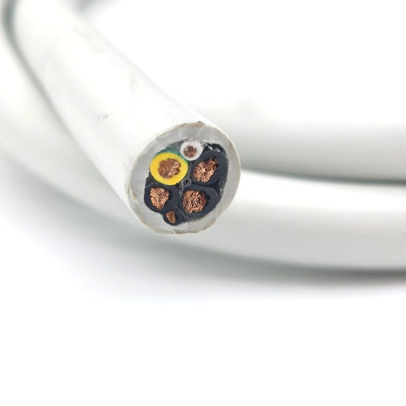
What separates a TC quotation from a PLTC quotation — product standard, voltage system, conductor temperature and the installation conditions each cable is permitted under.
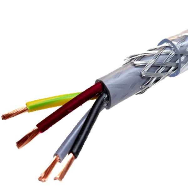
Tray cable is not one product. Type TC is a factory assembly of two or more insulated conductors, with or without associated bare or covered equipment grounding conductors, under a nonmetallic jacket — defined in NEC 336.2 and built to UL 1277. It is the 600 V power and control cable used in industrial tray systems. PLTC — power-limited tray cable — is a factory assembly of two or more insulated conductors rated 300 V, under a nonmetallic jacket, defined in NEC 725.2 and built to UL 13.
That difference is not cosmetic. TC lives in NEC Article 336 and PLTC lives in NEC Article 725, which are separate articles describing separate circuit classes, separate permitted uses and separate ampacity paths. PLTC belongs to the power-limited (Class 2 / Class 3) world; TC belongs to the power and control tray cable world. A quotation that rolls the two into one line — one voltage, one temperature — is describing a cable that does not exist, so we keep them on separate rows throughout this page.
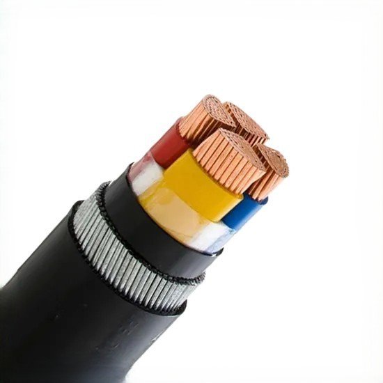
For TC the published conductor temperature is 90 °C dry and 75 °C in wet locations, with an emergency overload allowance to 105 °C and a short-circuit temperature of 250 °C. The construction behind those numbers is bare copper conductor, PVC insulation with a nylon layer, and a PVC overall jacket, in 18 AWG to 10 AWG with 2 to 37 conductors. PLTC is a 300 V product; the 105 °C figure that appears on PLTC datasheets is a manufacturer datasheet value, not a value the NEC sets for the article — we label it that way rather than dressing it up as a code number.
TC-ER is where the practical value sits. The ER stands for exposed run: with a TC-ER cable you may run the cable exposed between a tray and the equipment it feeds instead of enclosing it in conduit for the whole route, subject to the conditions of NEC 336.10(7) — industrial occupancy, continuous support and mechanical protection against damage, compliance with the crush and impact requirements of Type MC cable, the "TC-ER" marking on the cable, supports spaced not more than 1.8 m (6 ft) apart, and the equipment grounding conductor run within the cable. A transition between trays, or between a tray and equipment, may be made with not more than 1.8 m (6 ft) of unsupported length where the cable is not subject to physical damage. The ER marking is what buys the installer that route; without it, 336.12(2) keeps the cable inside the conduit or tray system.
Before an order is released we confirm four things together: which system is actually being purchased (TC, TC-ER or PLTC), the conductor count and size, the ambient and wet/dry conditions the ampacity is being read under, and whether the listed features that matter for your route — sunlight resistance, the direct burial identification, the TC-ER print legend — are on the construction you are buying. Anything on this page marked as pending confirmation is confirmed on the drawing and the form-type test report that come with the quotation.
More about the manufacturer: About SORIVO →
Type TC is 600 V under UL 1277 and NEC Article 336. PLTC is 300 V under UL 13 and NEC Article 725. We quote them as separate products with separate voltage, temperature and installation rows.
UL 1277 and UL 13 are the product standards that list the cable. NEC 336, 725 and 392 say where it may be installed. The NEC does not certify cable and we never describe it that way.
The ER marking permits exposed installation between tray and equipment under NEC 336.10(7) — industrial occupancy, continuous support, mechanical protection, Type MC crush and impact requirements, supports at 1.8 m (6 ft) or less.
PLTC conductors are rated 300 V per the NEC 725.2 definition. It is a power-limited circuit cable and is never quoted against the 600 V TC row.
90 °C in dry locations, 75 °C in wet locations, 105 °C emergency overload and 250 °C short circuit — the conditions matter, so they travel with the number.
Bare copper conductor, PVC insulation with a nylon layer over it, and a PVC overall jacket. 14–10 AWG insulation is Type THHN or THWN rated VW-1; 18–16 AWG is Type TFFN / TFN.
NEC 336.12(3) prohibits TC in direct sunlight unless the cable is identified as sunlight resistant. We state the marking, not a test duration we cannot support.
NEC 336.24: 4× OD up to 25 mm, 5× OD over 25 mm up to 50 mm, 6× OD over 50 mm, and 12× OD where the cable has a metallic shield.
Tray routes between a power source and the equipment it feeds — quoted against the actual NEC article for the circuit class.
TC and TC-ER tray runs feeding motors, drives, panelboards and field equipment in plants maintained by qualified persons.
TC-ER exposed runs from the tray to the machine, with supports at 1.8 m (6 ft) or less and mechanical protection where subject to damage.
Control and instrumentation circuits between switchgear, protection panels and auxiliary equipment.
Wet and damp locations where the 75 °C wet-location conductor temperature and moisture-resistant construction govern.
Tray circuits for plant areas where a hazardous-location classification applies — the Division 2 applicability of the specific construction is confirmed before it is offered.
Control, monitoring and power-limited circuits routed on tray above and behind the equipment.
DC and control tray runs between inverters, combiners, transformers and the plant control system.
Machine-level control interconnect where a jacketed, tray-rated multicore replaces individual conduit runs.
The parameter set our engineers quote from — with the standard each value comes from, and the system it belongs to.
| AWG | Conductors | Strands | Approx. OD 3-conductor | DC resistance @25 °C, Ω/ft | Ampacity 75 °C | Ampacity 90 °C |
|---|---|---|---|---|---|---|
| 18 | 2–37 | 16 (Class K) | — | — | — | — |
| 16 | 2–37 | 26 (Class K) | — | — | — | — |
| 14 | 2–37 | 7 (Class B) | 0.322 in | 0.00263 | 20 A | 25 A |
| 12 | 2–37 | 7 (Class B) | 0.369 in | 0.00166 | 25 A | 30 A |
| 10 | 2–37 | 7 (Class B) | 0.446 in | 0.00104 | 35 A | 40 A |
Reference construction values — the outside diameters, DC resistances and ampacities above are published values for comparable TC / TC-ER control cable constructions, not a fixed Sorivo catalogue; they are given so you can size a route before drawing review. Final construction data is confirmed on our drawing and form-type test report with the quotation. The 12 AWG 3-conductor row is highlighted. Ampacities are read from 2023 NEC Table 310.16 and are already adjusted for more than three current-carrying conductors; they are not adjusted for the small-conductor overcurrent limits of NEC 240.4(D), which cap 14 AWG at 15 A, 12 AWG at 20 A and 10 AWG at 30 A unless the installation falls under one of the exceptions in that section. Published outside diameter and resistance values exist only for the 14, 12 and 10 AWG rows in this table; for 18 and 16 AWG we list the strand counts, and the diameters and resistances for those sizes are confirmed on the drawing.
| General Information | |
| Product Name | Tray cable — Type TC / TC-ER (600 V power and control) and Type PLTC (300 V power-limited) |
| Type TC / TC-ER Product Standard | UL 1277 — Electrical Power and Control Tray Cables (with optional optical-fiber members) |
| Type PLTC Product Standard | UL 13 — Power-Limited Circuit Cables |
| Installation Standards | TC / TC-ER: NEC Article 336. PLTC: NEC Article 725. Cable trays: NEC Article 392 |
| Test Method Reference | UL 1581 — Reference Standard for Electrical Wires, Cables, and Flexible Cords (the test methods behind flame and sunlight performance, not a product listing) |
| Definition — Type TC | A factory assembly of two or more insulated conductors, with or without associated bare or covered equipment grounding conductors, under a nonmetallic jacket (NEC 336.2) |
| Definition — Type PLTC | A factory assembly of two or more insulated conductors rated at 300 volts, with or without associated bare or insulated equipment grounding conductors, under a nonmetallic jacket (NEC 725.2) |
| Conductor Range & Count | 18 AWG to 10 AWG, 2 to 37 conductors (reference range of the comparable constructions; the range we build to is confirmed on the quotation) |
| Type TC & TC-ER Ratings — 600 V System | |
| Rated Voltage — TC / TC-ER | 600 V |
| Conductor Temperature — Dry Locations | 90 °C |
| Conductor Temperature — Wet Locations | 75 °C |
| Emergency Overload Temperature | 105 °C |
| Short-Circuit Temperature | 250 °C |
| Conductor Material | Bare copper |
| Conductor Identification | Control cable conductor identification by printed numbers to a published method, or to the customer requirement confirmed at order |
| Ampacity Basis | 2023 NEC Table 310.16, adjusted for more than three current-carrying conductors; small conductors remain subject to the overcurrent limits of NEC 240.4(D) |
| Ampacity Path — 14 AWG and Larger | NEC 392.80(A) for cables installed in a cable tray (NEC 336.80) |
| Ampacity Path — 18 and 16 AWG | NEC Table 402.5 when installed in a tray; NEC 310.14 when installed outside a tray (NEC 336.80) |
| Type PLTC Ratings — 300 V System | |
| Rated Voltage — PLTC / PLTC-ER | 300 V (the voltage stated in the NEC 725.2 definition of Type PLTC) |
| Conductor Temperature | 105 °C — manufacturer datasheet value for North American PLTC constructions. This figure is not established by NEC Article 725 or by UL 13, and we quote it as a datasheet value rather than a code requirement |
| Product Standard | UL 13 — Power-Limited Circuit Cables |
| Temperature Range — Fixed Installation | −40 °C to +105 °C — manufacturer datasheet value for the unscreened PLTC / ITC construction. Not a code-derived figure; the value for the construction supplied is confirmed on its datasheet |
| Tray Installation Rules | NEC 725.135(J), Table 725.154 and 725.179(E) |
| PLTC-ER Exposed Runs | Permitted where the cable includes an equipment grounding conductor |
| Sunlight Exposure | PLTC not identified as sunlight resistant is not permitted in direct sunlight; cable identified for the purpose is used where exposed, per NEC 336.12(3) and the Article 725 tray provisions |
| Construction | |
| Conductor | Bare copper, stranded |
| Stranding — 14 / 12 / 10 AWG | 7 strands, Class B compressed, per ASTM B3 and B8 |
| Stranding — 16 AWG | Class K bare copper, 26 strands, per ASTM B3 and B174 |
| Stranding — 18 AWG | Class K bare copper, 16 strands, per ASTM B3 and B174 |
| Insulation | PVC with a nylon layer |
| Insulation Type — 14 / 12 / 10 AWG | Type THHN or THWN, rated VW-1 |
| Insulation Type — 18 / 16 AWG | Type TFFN / TFN |
| Overall Jacket | PVC, nonmetallic |
| Metallic Elements (NEC 336.100) | Metallic sheaths or armouring as defined in NEC 330.116 are not permitted over or under the nonmetallic jacket. A metallic shield is permitted over the assembled conductors, under the outer jacket, or both |
| Print Legend | Marked with the conductor size and count, the type designation, the temperature rating, "SUNLIGHT RESISTANT" where that identification applies, and the voltage rating — the exact legend for your construction is confirmed on the drawing |
| Installation — NEC Conditions | |
| In Cable Tray | Permitted, including through mechanical discontinuities not exceeding 300 mm (1 ft) in the tray system — NEC 336.10(2) |
| Exposed Runs — Basis | NEC 336.10(7): permitted between a cable tray and the equipment served only where all of the following are met — the cable is Type TC-ER; the installation is in an industrial establishment where conditions of maintenance and supervision ensure that only qualified persons service the installation; the cable is supported continuously and protected against physical damage by an approved means (struts, angles, channels); the cable complies with the crush and impact requirements of Type MC cable and is marked "TC-ER"; the cable is secured and supported at intervals not exceeding 1.8 m (6 ft); and an equipment grounding conductor is provided within the cable |
| Tray-to-Equipment Transition | Where not subject to physical damage, a transition between cable trays, or between a cable tray and the equipment served, may be made with not more than 1.8 m (6 ft) of unsupported cable — NEC 336.10(7) Exception |
| Aerial, Outdoors | Permitted where supported by a messenger wire — NEC 336.10(4) |
| Direct Burial | Permitted only where the cable is identified for such use — NEC 336.10(10). Direct burial is not a blanket property of tray cable; the identification has to be on the cable you are buying |
| Wet Locations | Type TC is required to be moisture resistant and resistant to the corrosive media present — NEC 336.10(8) |
| Direct Sunlight | Prohibited unless the cable is identified as sunlight resistant — NEC 336.12(3) |
| Outside Conduit or Tray | Prohibited other than as permitted by NEC 336.10(4), (7), (9) and (10) — NEC 336.12(2) |
| Minimum Bend Radius — No Metallic Shield | 4× outside diameter for cables 25 mm (1 in) or less; 5× outside diameter over 25 mm up to and including 50 mm; 6× outside diameter over 50 mm — NEC 336.24 |
| Minimum Bend Radius — Metallic Shield | 12× outside diameter — NEC 336.24 |
| Environmental & Fire | |
| Flame Rating | VW-1 rated insulation |
| Vertical Tray Flame Test | IEEE 1202 / FT4 (70,000 Btu/hr) is the vertical tray flame test method commonly referenced for this cable family; it is a test method, not a certification, and the result for the construction supplied is confirmed on our test report |
| Sunlight Resistance | Cable manufactured with a sunlight resistant jacket and marked accordingly, for use where exposed to direct sunlight as permitted by NEC 336.12(3) |
| Chemical & Moisture | Moisture resistant and resistant to the corrosive media present; the suitability of the jacket for a specific chemical exposure is confirmed on request |
| Silicone | Silicone-free construction |
| Hazardous Locations | A Division 2 applicability is published for comparable constructions; whether it applies to the cable we supply for your project is confirmed before it is offered as a property |
| Low Smoke Zero Halogen (LSZH) | Not part of the UL 1277 or UL 13 requirement. An LSZH jacket belongs to a different standards family (for example IEC 60754 / IEC 61034 / EN 50267) and is quoted, if available, as a separate construction under those standards — never as a UL 1277 property |
| Commercial & Logistics | |
| MOQ | 100 m — sample orders accepted |
| Lead Time | 7–20 working days; stocked configurations 3–5 days |
| Standard Lengths | 100 m / 500 m / 1000 m per drum; cut lengths on request |
| Packaging | Wooden drum, steel-wood drum or coil per order |
This table deliberately keeps TC / TC-ER (600 V) and PLTC (300 V) in separate groups: they are different products under different product standards and different NEC articles, and a value from one system must not be read across to the other. Routine factory inspection values are not published here: they are production checks on the length you receive, not published properties of the product. Crush and impact compliance is required by NEC 336.10(7)(d) by reference to Type MC cable; the NEC sets no numeric value there, so none is quoted. Please note: MOQ, lead time, stock position and standard drum lengths in the Commercial & Logistics group follow the convention used for our other engineered cables and are pending factory confirmation — they are confirmed with the quotation for your specific construction. Values described as reference construction values are published values for comparable constructions; final construction data is confirmed on our drawing and form-type test report.
The product standard for electrical power and control tray cables, the standard behind the 600 V Type TC and TC-ER constructions. It lists the cable; the NEC articles say where it may be installed. The certificate and the scope that applies to your construction come with the quotation.
Request TC / TC-ER documents →The product standard for power-limited circuit cables, the standard behind the 300 V PLTC construction. Quoted against its own voltage and its own NEC article — Article 725 — not against the Type TC row.
Request PLTC documents →The reference standard for the test methods used on wires, cables and flexible cords — including the flame and sunlight exposure methods behind the VW-1 and sunlight-resistant markings. It is a method standard, not a product listing.
Request test reports →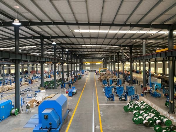
Conductor, insulation, jacket and print legend are controlled against the approved drawing, and every length is routine tested before it is drummed.
Tell us the system (TC, TC-ER or PLTC), conductor count and size, voltage, and the installation conditions the cable runs under.
We confirm the construction, the print legend, the ampacity basis and the quotation within one working day.
Drawing and sample length for fit and qualification, including any listed identification your route depends on.
7–20 working days for standard configurations, with routine testing on every length before drumming.
Drum lengths to order, shipping documents, test records and after-sales support.
Tell us the system (TC, TC-ER or PLTC), conductor count and size, and the installation conditions — we reply within one working day.
The more detail you give, the faster and more accurate our quotation. Our engineers reply within one working day.
Thanks — our engineers will reply within one working day.