
Rated Current vs. Actual Current in Power Cables: The 40–60% Gap You Can't Afford to Ignore
Here's a scenario I've seen play out more times than I care to count.
A project engineer picks a cable from the manufacturer's ampacity table. Say, a 95 mm² copper XLPE cable — rated at 278 A per IEC 60364-5-52, three-phase, in free air (Method E). Looks fine for the 220 A load. Job done, right?
Fast-forward to commissioning. Six months later, the cable run is warm — too warm. The IR camera shows conductor temps pushing 85 °C. Not quite tripping the protection, but nobody's comfortable. The engineer re-checks his calcs. They're correct against the table. So what gives?
The thing is, the ampacity table isn't wrong. But it's also not right for his installation.
His cables run through a rooftop conduit in Dubai. Ambient hits 48 °C in summer. There are six circuits in that conduit. The conduit sits on a dark membrane roof. Combine those factors, and that 278 A rated cable has an effective ampacity of roughly 145 A — nearly half the nameplate value.
This isn't a rare edge case. It's the norm. In my experience working across solar, industrial, and infrastructure projects, the gap between a cable's published rated current and its actual usable ampacity in the field consistently runs between 40% and 60%. And most engineers aren't accounting for it properly.
Let's walk through the numbers, the standards, and — most importantly — what to do about it.
Where Does "Rated Current" Even Come From?
Before we talk about the gap, we need to understand what the "rated current" on a cable datasheet actually represents. It's not a physical property of the cable. It's the result of a calculation under a specific set of assumptions.
The IEC 60287 Framework
The international standard for cable ampacity calculations is IEC 60287 (latest edition: IEC 60287-1-1:2023). The core formula for steady-state operation looks like this:
I = √( Δθ - Wd[0.5T1 + n(T2 + T3 + T4)] ) / ( RcT1 + nRc(1+λ1)T2 + nRc(1+λ1+λ2)(T3 + T4) )
Where Δθ is the allowable temperature rise, Rc is AC resistance, T1–T4 are thermal resistances, and λ1/λ2 are loss factors.
This formula is rigorous. The problem isn't the math — it's the input assumptions.
The Reference Conditions
When you see a "278 A" rating for a 95 mm² XLPE cable, it was calculated using these standard reference conditions:
| Parameter | Reference Value (IEC 60364-5-52 for LV / IEC 60287-3-1 for MV) | What That Assumes |
|---|---|---|
| Ambient air temperature | 30 °C | Air-conditioned indoor environment |
| Ambient ground temperature | 20 °C | Moderate climate, shaded soil |
| Soil thermal resistivity | 2.5 K·m/W (LV) / 1.5 K·m/W (MV) | Moist, average soil |
| Burial depth | 0.7 m (LV) / 0.8 m (MV) | Standard trench depth |
| Conductor temperature | 70 °C (PVC) / 90 °C (XLPE) | Insulation thermal limit |
| Load factor | 100% (continuous) | Current flows at full rated value indefinitely |
| Number of circuits | 1 circuit, 3 conductors | No mutual heating from adjacent cables |
Now ask yourself: when was the last time your installation matched all seven of those assumptions perfectly?
I've been on sites across Asia, the Middle East, and Europe. I can count on one hand the projects where even four of these lined up. The rest of the time, every parameter that deviates from the reference conditions eats into your usable ampacity.
Conductor and Insulation Materials — the Starting Point
The base ampacity also depends heavily on what the cable is made of. Here's how the common options compare:
| Material / Type | Max Conductor Temp | Relative Ampacity (vs. PVC baseline) | Key Trade-off |
|---|---|---|---|
| PVC insulated copper | 70 °C | 1.00× (baseline) | Lowest cost, shortest thermal life, not UV-stable |
| XLPE insulated copper | 90 °C | ~1.15–1.22× (depends on installation) | Higher thermal capacity, 25+ year design life |
| LSZH XLPO (halogen-free) | 90 °C | ~1.20× | Mandatory for confined spaces, slightly higher cost |
| EPR insulated copper | 90 °C | ~1.22× | Excellent flexibility, good for dynamic applications |
| Bare copper conductor | — | Baseline (RDC) | Oxidizes over time, increased resistance |
| Tinned copper conductor | — | ~same RDC | Corrosion protection, solderable, IEC 60228 Class 5/6 |
That 15–22% bump from PVC to XLPE looks attractive — and it's real, provided your installation lets the cable reach 90 °C without problems. But here's the catch: accessories and terminations (connectors, switchgear, junction boxes) are often rated at 70 °C or 75 °C. So even if the cable can take 90 °C, the system may be limited by the weakest thermal link. Mind you, this is one of the most overlooked constraints in real-world cable sizing.
The Derating Gauntlet: What Actually Happens in the Field
This is where the rubber meets the road. Every real-world condition that differs from the IEC reference gets a correction (derating) factor. These factors multiply, not add. A few seemingly modest deviations can compound into a massive gap. For a complete breakdown by installation method, see our guide on cable ampacity by installation method.
Factor 1: Ambient Temperature (k₁)
The biggest single contributor, hands down. A cable's ampacity is fundamentally limited by how fast it can shed heat. Hotter environment → less heat dissipation → lower ampacity.
| Ambient Temp | Correction Factor (PVC 70 °C) | Correction Factor (XLPE 90 °C) |
|---|---|---|
| 25 °C | 1.06 | 1.04 |
| 30 °C (reference) | 1.00 | 1.00 |
| 35 °C | 0.94 | 0.96 |
| 40 °C | 0.87 | 0.91 |
| 45 °C | 0.79 | 0.87 |
| 50 °C | 0.71 | 0.82 |
| 55 °C | 0.61 | 0.76 |
| 60 °C | 0.50 | 0.71 |
| 65 °C | — | 0.65 |
| 70 °C | — | 0.58 |
What this means in practice: Take that 95 mm² XLPE cable rated at 278 A. At 45 °C ambient (common in Middle Eastern or Australian rooftops), the usable ampacity drops to 278 × 0.87 = 242 A. At 50 °C: 278 × 0.82 = 228 A. Already a 20% loss — and we haven't applied any other factors yet.
Factor 2: Grouping / Mutual Heating (k₂)
Multiple circuits running together heat each other. The impact is bigger than most engineers assume:
| Number of Circuits (bunched in air) | Derating Factor |
|---|---|
| IEC 60364-5-52 (by circuit — 1 circuit = 3 conductors) | |
| 2 circuits (6 conductors) | ~0.80 |
| 3 circuits (9 conductors) | ~0.70 |
| 4 circuits (12 conductors) | ~0.65 |
| 5 circuits (15 conductors) | ~0.60 |
| 6 circuits (18 conductors) | ~0.55 |
| NEC Table 310.15(C)(1) (by current-carrying conductor count) | |
| 4–6 conductors | 0.80 |
| 7–9 conductors | 0.70 |
| 10–20 conductors | 0.50 |
| 21–30 conductors | 0.45 |
Apply this to our 95 mm² cable example. At 50 °C ambient (0.82) with 4 circuits grouped (0.70):
278 × 0.82 × 0.70 = 159 A. We've lost 43% of the nameplate rating.
Factor 3: Solar Radiation / Rooftop Effect
This is where it gets brutal. The NEC (National Electrical Code) requires an explicit temperature adder for conduits on rooftops. Note: this rule was revised between editions — the +22 °C adder applies per NEC 2017 and earlier; under NEC 2020 the +33 °C adder is retained only for conduits within 7/8 in (22 mm) of the roof surface, while conduits above that height no longer carry a mandatory adder in all cases.
- Conduit ≤ 13 mm above roof: add +33 °C to ambient (all editions)
- Conduit 13–90 mm above roof: add +22 °C (NEC 2017 and earlier)
Take Phoenix, Arizona — 43 °C design ambient. Add +22 °C for a conduit at 50 mm height → 65 °C effective ambient. Correction factor for a 90 °C XLPE cable at 65 °C: 0.65.
If we combine all three factors for that same 95 mm² cable on a Phoenix rooftop with 6 conductors in one conduit:
278 A × 0.65 (temp) × 0.80 (grouping) = 145 A
That's 48% below the nameplate 278 A. This is not a theoretical worst-case — this is a standard commercial rooftop installation in a hot climate.
Factor 4: Depth of Burial (k₄)
For underground cables (including 0.6/1kV LV and MV distribution), deeper burial = less heat dissipation. Reference depth is 0.7 m (LV) or 0.8 m (MV):
| Depth | Factor (direct buried, LV) |
|---|---|
| 0.5 m | 1.00 |
| 0.7 m (ref) | 0.98 |
| 1.0 m | 0.94 |
| 1.5 m | 0.91 |
| 2.0 m | 0.89 |
| 3.0 m | 0.87 |
Not the biggest factor, but when you're already at 50% of nameplate, every percent counts.
Factor 5: Soil Thermal Resistivity (k₅)
This is the underground equivalent of the rooftop temperature adder — and it's often underestimated.
| Soil Type | Thermal Resistivity | Derating Factor (relative to ref) |
|---|---|---|
| Wet clay / peat | 0.8 K·m/W | ~1.10 (can uprate) |
| Average soil (reference) | 1.0–1.2 K·m/W | 1.00 |
| Sandy soil | 1.5 K·m/W | ~0.83 |
| Dry sandy soil | 2.0 K·m/W | ~0.73 |
| Very dry / rocky | 2.5 K·m/W | ~0.66 |
| Extreme (dry desert) | 3.0 K·m/W | ~0.60 |
In desert solar projects I've worked on, soil thermal resistivity of 2.5–3.0 K·m/W is unfortunately common. That 0.60–0.66 factor alone means you lose a third of your rated capacity before you even switch the system on.
Factor 6: Harmonics (k₆)
With the rise of LED lighting, variable frequency drives, and power electronics, non-sinusoidal currents are everywhere. Triplen harmonics (3rd, 9th, 15th) don't cancel on the neutral — they add. The neutral conductor can end up carrying up to 1.7× the phase current.
The NEC doesn't provide explicit harmonic derating factors (a significant gap, in my opinion). BS 7671 Appendix 4 (Table 5A.4) does — roughly 0.86 at 20% third harmonic content. In practice, I've seen neutrals in commercial buildings running 30% hotter than the phase conductors, and nobody accounted for it in the initial sizing.
Market Standard vs. SORIVO: Where the Difference Shows
When you're sourcing cables for a project where the derating gap matters — and honestly, that's every project — the quality of the cable itself determines whether those derating factors stay stable over 25 years or get worse. Here's what we see in the field:
| Characteristic | Market Commodity / Economy Grade | SORIVO Premium Grade |
|---|---|---|
| Conductor | Bare copper (oxidizes over time, resistance drifts up) | Tinned copper (IEC 60228 Class 5/6 — stable RAC over 25 years) |
| Insulation | PVC (5–8 year thermal life at rated temp, 70 °C limit) | XLPE insulated, LSZH sheathed (25-year design life, −40 °C to +90 °C ambient, +125 °C max. conductor / short-circuit) |
| UV resistance | Minimal stabilizers — embrittlement in 2–3 years outdoors | Carbon black 2.6% ± 0.25% + UV stabilizers — HD 605 S1, 1000h xenon arc, ≥85% retained |
| Temperature derating | Assumes 70 °C max — heavy derating above 40 °C | 90 °C continuous — significantly more thermal headroom (see table above) |
| Certification | Self-declared CE (no test data) | TÜV / UL / KEMA / BASEC — third-party verified test reports |
| Traceability | None — unable to trace batch | Metre-mark printing, batch traceable to production date and raw material lot |
| Warranty | 1–5 years | 25 years |
The real-world impact: A commodity-grade PVC cable operating at 50 °C ambient loses about 29% of its rated ampacity just from temperature. Add grouping and it's worse. A premium XLPE cable at the same temperature loses ~18% — and has a built-in margin because its 90 °C rating leaves more room before the insulation degrades. That's the difference between a cable that barely works on paper and one that actually works in the field.
Case Studies: The Gap in Real Projects
Case 1: Solar PV Feeder — Cyclic Loading (the Hidden Upside)
Here's where it gets interesting. I mentioned earlier that the IEC 60287 steady-state rating assumes 100% load factor — the peak current flows continuously. But solar doesn't work that way.
A 240 mm² aluminium XLPE cable in a buried solar collector system has a steady-state rating of roughly 290 A (per IEC 60287). The actual solar load profile peaks at ~238 A for about 4 hours midday and drops to near-zero overnight. For projects using H1Z2Z2-K solar cable (EN 50618), the 90 °C XLPE insulation provides additional thermal headroom for this cyclic duty.
Here's the thing: the cable never reaches steady-state temperature. Because of thermal inertia in the soil and cable mass, the conductor settles at around 50 °C — a full 40 °C below the 90 °C XLPE limit. That's a huge margin.
IEC 60853 (cyclic rating) allows a cyclic rating factor of 1.3–1.6× the steady-state rating for solar duty cycles. For that 240 mm² cable, the permissible peak current under cyclic loading could be 375–460 A — well above the array's actual peak. This is the rare case where the rated current is too conservative.
But — and this is a big but — this only applies if you've done the dynamic thermal modeling. Most projects don't. They size for steady-state and oversize the cable unnecessarily. Or worse, they use the steady-state rating as a hard limit without realizing they could go higher safely.
Case 2: Rooftop Commercial PV — Multiplier Stacking
Using the NEC framework (common in North American and Asia-Pacific projects), here's what happens to a 10 AWG (5.3 mm²) PV wire rated at 40 A (90 °C column):
| Step | Calculation | Result |
|---|---|---|
| Base ampacity (10 AWG, 90 °C) | NEC Table 310.16 | 40 A |
| Rooftop temperature adder | 43 °C ambient + 22 °C = 65 °C effective | 65 °C |
| Correction factor at 65 °C | 0.65 (90 °C column) | 0.65 |
| 6 conductors in conduit | NEC Table 310.15(C)(1): 6 conductors → 80% | 0.80 |
| Adjusted ampacity | 40 × 0.65 × 0.80 | 20.8 A |
| NEC 690.8: continuous load × 1.25 | Required ampacity = Isc × 1.25 | ÷1.25 applied in sizing |
| Usable for actual load | 20.8 ÷ 1.25 | 16.6 A continuous |
That's a 58% reduction from the nameplate 40 A. The same 10 AWG cable that looks perfectly fine for a 9.5 A module string on paper can barely handle two strings in practice — and that's before voltage drop.
Case 3: Singapore Underground — Hotspot Remediation
A 230 kV, 500 MVA underground circuit in Singapore was operating at only 400 MVA — a 20% forced derating — because of hotspots caused by congested installation, poor backfill, and high ambient at shallow depth.
The utility (SP PowerGrid) deployed Distributed Temperature Sensing (DTS) to locate the hotspots, replaced the backfill, and installed drainage. Result: full 500 MVA restored — a 25% gain — at a cost of S$0.25 million vs. S$30 million for a new circuit. That's a 120:1 ROI on solving the real vs. rated gap.
The Hidden Cost of Ignoring the Gap: TCO
Getting the rated-vs-actual calculation wrong cuts both ways. Let's quantify both directions.
Cost of Oversizing (Conservative Design)
When you size cables based on the nameplate rating without rigorous derating, but then apply overly conservative rules of thumb, you oversize. A lot.
| Parameter | Conservative Design (1.56×) | Engineered Design (proper derating analysis) | Difference |
|---|---|---|---|
| Conductor size (100 A design) | 4/0 AWG (≈107 mm²) | 3/0 AWG (≈85 mm²) | One size up |
| Copper mass per 100 m | ~214 kg | ~170 kg | −44 kg |
| Material cost at ~$8/kg Cu | ~$1,712 | ~$1,360 | −$352 (−21%) |
| Conduit / tray size | Larger (1–2 sizes up) | Standard | Additional savings |
| Installation labor | Heavier, harder to pull | Lighter, easier | ~15–20% less |
| Termination hardware | Larger lugs, connectors | Standard | Minor savings |
| Total savings per 100 m run | ~$500–700 |
For a 10 MW solar farm with 5 km of DC cabling, oversizing by one gauge adds $25,000–$35,000 in unnecessary copper cost — plus the labor and hardware premiums. This is why utility-scale projects routinely apply NEC 690.8(B)(2) engineering analysis to demonstrate that the maximum continuous current is lower than the blanket 1.25× multiplier would suggest, often saving one full cable size. For a full breakdown, see our cable TCO analysis guide.
Cost of Under-sizing (Ignoring Derating)
This is the more dangerous direction. When you use nameplate ratings without derating, you get:
- Insulation degradation: For every 10 °C above the rated conductor temperature, XLPE insulation life approximately halves (per IEC 60216 thermal ageing theory, Montsinger rule). A cable running at 100 °C instead of 90 °C will last ~25 years → ~12 years.
- I²R losses: Higher resistance at elevated temperature means 2–5% higher operational losses over the cable's lifetime.
- Voltage drop penalties: Under-sized cable → higher voltage drop → inverters trip off earlier → energy yield loss of 0.5–2% annually.
- Fire risk: In extreme cases (PVC undersized in bundling), conductor temperatures can exceed 110 °C, approaching PVC decomposition temperature.
| Failure Mode | Trigger | Quantified Impact |
|---|---|---|
| Insulation aging acceleration | 10 °C over temperature limit | 25-year design life → ~6 years (per IEC 60216, every 10 °C halves XLPE life) |
| Energy losses (over-lifetime) | Under-sized by 1 AWG, 50 m run, 100 A | ~$1,200–$2,400 additional losses over 25 years |
| Emergency replacement | Premature cable failure | 3–8× material cost (trenching, re-pulling, downtime) |
| Production loss (solar farm) | Inverter tripping on voltage drop | 0.5–2% annual yield loss → $5,000–$20,000/year for 10 MW farm |
| AHJ rejection / redesign | Non-compliant sizing | $5,000–$15,000 in re-engineering and permitting delays |
On the flip side, getting the sizing right — with proper derating analysis, site-specific input parameters, and quality cables that maintain their rated performance over 25 years — is one of the highest-ROI engineering decisions you can make on a project.
Voltage Drop Quick Reference Table
Voltage drop is the second constraint (after ampacity) that determines minimum cable size. For long DC runs in solar farms, it often governs. Here's a quick-reference table for copper cables at 60 °C operating temperature, DC system (or AC unity power factor):
| Cable Size (mm²) | Resistance (mΩ/m at 60 °C) | Voltage Drop at 10A per 10m (%) — 48V DC | Voltage Drop at 10A per 10m (%) — 600V DC | Voltage Drop at 10A per 10m (%) — 1500V DC |
|---|---|---|---|---|
| 4 mm² | 5.34 | 2.23% ⚠️ | 0.18% | 0.07% |
| 6 mm² | 3.56 | 1.48% | 0.12% | 0.05% |
| 10 mm² | 2.12 | 0.88% | 0.07% | 0.03% |
| 16 mm² | 1.33 | 0.55% | 0.04% | 0.02% |
| 25 mm² | 0.84 | 0.35% | 0.03% | 0.01% |
| 35 mm² | 0.61 | 0.25% | 0.02% | 0.01% |
Quick rule of thumb: For every 10 m of 4 mm² cable at 10 A on a 48 V system, expect ~2% voltage drop. At 1500 V DC, the same cable loses only 0.07% — that's why utility-scale solar farms use 1500 V architecture. Note: "10m" in the table refers to route length (1-way), meaning a total wire length of 20 m for a 2-wire DC circuit. This matches the round-trip (both conductors) voltage drop a connected device sees. For a full voltage drop calculator, see our DC cable sizing guide for solar PV.
Cable Selection Decision Matrix
Not sure which cable type fits your environment? Here's a quick-reference matrix based on environmental factors:
| Environmental Factor | Recommendation | Key Standard | Why |
|---|---|---|---|
| Rooftop solar, high ambient (>45 °C) | H1Z2Z2-K (EN 50618), tinned copper, XLPO sheath | EN 50618, HD 605 S1 | UV resistance, 90 °C rating, tinned conductor prevents corrosion |
| Buried direct, moist soil | XLPE/SWA/PVC or XLPE/SWA/LSZH | IEC 60502-1, BS 5467 | SWA armour handles mechanical stress; moisture-resistant jacket |
| Desert / dry sandy soil | XLPE/SWA/LSZH with thermal backfill | IEC 60287 (k₅ calculation) | Soil resistivity >2.5 K·m/W requires upsizing or backfill improvement |
| Indoor switchgear / panel | H07V-R (single-core) or tri-rated panel wire | BS EN 50525-2-31, BS 6231 | Flame retardant, flexible for compact routing |
| Data centre / confined space | LSZH armoured or LSZH single-core | BS 6724, IEC 60332-1-2 | Zero halogen — critical for human safety in enclosed areas |
| BESS container (outdoor) | Storage cable to TÜV 2PfG 2693 | TÜV 2PfG 2693 | Electrolyte and cooling fluid resistance; 1500 V DC rating |
| Offshore / coastal / high humidity | SWA/AWA with LSZH jacket, tinned copper conductor | IEC 60228 Class 2, BS 5467 | Corrosion resistance; tinned copper prevents galvanic attack |
Pre-Installation Checklist: 8 Critical Checks
Before you pull that cable, run through this checklist. Each item directly affects whether your cable's actual ampacity matches its design value:
- Ambient temperature verified? — Measure actual ambient at the installation location during the hottest part of the day. Don't rely on weather station data alone — roof surfaces can be 15–25 °C hotter than air temperature.
- Grouping factor confirmed? — Count every current-carrying conductor in each conduit, tray, or bundle. Remember to count neutrals that carry harmonic currents.
- Burial depth and soil type checked? — For direct burial, verify actual soil type (clay, sand, rock) and measure thermal resistivity if >1.5 K·m/W is suspected.
- Cable armour and sheath continuity tested? — Use a DC insulation tester at 500 V or 1000 V between conductor and earth. Record the reading for commissioning documentation.
- Bending radius within limits? — For armoured cables, minimum bending radius = 12× overall diameter (IEC 60502-1). For single-core armoured, 15×. Measure, don't estimate.
- Derating factors all applied? — Create a full derating calculation sheet: Iadj = Itable × k₁ × k₂ × k₃ × k₄ × k₅ × k₆. Verify the final value exceeds your maximum continuous load.
- Termination temperature rating checked? — Switchgear terminals are typically 70 °C or 75 °C. Even with 90 °C XLPE cable, the system ampacity is limited by the lowest-rated component.
- Voltage drop at full load calculated? — For long runs, voltage drop often governs cable size before ampacity does. Calculate at full load current and verify against applicable limits (typically 3% for IEC, 2% branch / 3% total for NEC).
For a more comprehensive pre-installation checklist covering tension monitoring, pulling lubricants, and field testing, see our cable laying equipment and pre-installation guide.
How to Verify Cable Quality in the Field
Price and paperwork alone won't tell you if a cable will hold its rated ampacity after 5 years in the field. Here's what I look for when I'm auditing a cable supply:
- Sheath feel and roundness: A uniform, dense sheath that springs back after compression suggests good compound mixing and proper extrusion. Soft or irregular sheaths are a red flag.
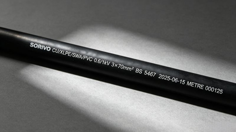
- Print legibility and metre marking: If the ink rubs off with light finger pressure, what happens after a year in a hot conduit? Legible, permanent metre marks every metre indicate quality manufacturing. Check three points along the coil — if one section has faded printing, the cable may be from mixed production lots.
- Conductor — is it tinned? Not all tinned copper is equal. Rub the surface gently. A uniform matte silver finish with no bare copper patches is what you want. Spotty or uneven coating suggests poor process control.
- Eccentricity: Look at the cross-section. The insulation should be concentric around the conductor — not thinner on one side. High eccentricity means the insulation is the minimum thickness on the thin side and unnecessarily thick on the other, wasting material and creating thermal non-uniformity.
- Smoke and halogen testing: For LSZH cables, a simple flame test (in a fume hood — do this safely) should produce minimal white smoke. Dense black or yellow smoke indicates halogen content. IEC 61034-2 requires ≥60% light transmittance.
- Traceability paperwork: Ask for the batch number and date code. A manufacturer that can trace a reel to its raw material lots and QC test results has a real quality system. One that can't — well, you're buying on faith. For a step-by-step guide to verifying third-party certifications, read our article on how to verify TÜV/UL certification for solar cables.
Bridging the Gap: What to Do About It
So what's the takeaway? The gap between rated and actual cable current isn't a design flaw in the standards — it's a mismatch between standardized assumptions and site-specific reality. And it's your job as the engineer or specifier to bridge that gap.
My recommendation:
- Don't trust nameplate ampacity. Treat it as a starting point, not an answer. Always apply derating factors for your site conditions. Our ampacity derating guide covers temperature, altitude, and grouping factors in more detail.
- Model the actual duty cycle. For solar, wind, and other variable-load applications, IEC 60853 cyclic rating can unlock 30–60% more capacity than steady-state ratings suggest — safely.
- Choose the right cable for the environment. A 90 °C XLPE cable has significantly more thermal headroom than a 70 °C PVC cable at high ambient temperatures. The premium is usually worth it.
- Verify what you're buying. Third-party certification (TÜV, UL, KEMA, BASEC), traceable production, and consistent print marking are signs of a cable that will actually perform as rated — for 25 years.
- Do the TCO math. The cheapest cable upfront is almost never the cheapest over 25 years, especially when you factor in the ampacity gap and how it widens as the cable degrades.
Need Help Sizing Cables for Your Project?
Our engineering team can review your project specifications, apply correct derating factors per IEC 60287 and IEC 60364-5-52, and recommend the optimal cable configuration — not oversized, not under-sized, just right.
Get Engineering Support Browse Cable RangeEmail: sale@sorivocable.com | Tel: +86 192 8290 5529

Frequently Asked Questions
Q: If my cable's rated ampacity is 278 A but I'm only drawing 220 A, why is it overheating?
A: The rated ampacity assumes specific reference conditions (30 °C ambient, clipped direct, no grouping). If your cable is in a hot environment, bundled with other circuits, or running through an insulated wall, the effective ampacity can be well below 220 A even though the nameplate says 278 A. Apply the derating factors for your actual installation conditions — you might find the real limit is 150–180 A.
Q: Can I use PV cables for BESS (battery energy storage) applications?
A: It depends. Standard PV cables (EN 50618 / H1Z2Z2-K) are designed for outdoor solar use with UV resistance and 1.5 kV DC rating. BESS environments add electrolyte exposure, cooling fluid contact, and high-humidity cycling. TÜV 2PfG 2693 specifically addresses these conditions. If your BESS operates in a controlled indoor environment with no chemical exposure, PV cables may suffice. But for containerized or outdoor BESS, you should use cables certified to 2PfG 2693.
Q: Why does the NEC require 1.56× oversizing for PV conductors — is it really necessary?
A: The 1.56× factor comes from two stacked 1.25× multipliers, both from Article 690.8 — one for irradiance margin (NEC 690.8(A): Isc × 1.25) and one for continuous load / OCPD sizing (NEC 690.8(B): × 1.25). The conservatism is intentional: modules can produce >1000 W/m² current under cloud-edge effect or reflection (snow, water), and continuous loads need thermal headroom. That said, for systems over 100 kW, NEC 690.8(B)(2) allows engineering analysis to reduce the factor if you can demonstrate the maximum 3-hour current is lower. Most utility-scale plants do this and save one cable size.
Q: What's the difference between steady-state and cyclic cable rating — and when should I care?
A: Steady-state rating (IEC 60287) assumes 100% load factor — the cable carries peak current continuously. Cyclic rating (IEC 60853) accounts for thermal inertia: the cable and surrounding medium take time to heat up. For loads with a short peak and long off-peak (solar PV, wind, EV charging, cranes), the cyclic rating can be 30–60% higher than steady state. Use cyclic rating when your load profile has a clear on/off pattern. Don't use it for baseload applications (data centers, continuous industrial processes).
Q: How do I know if a cable I'm buying will actually deliver its rated ampacity for 25 years?
A: Look for three things: (1) Third-party certification — TÜV, UL, KEMA, or BASEC, not just a self-declared CE mark. (2) Traceability — metre-mark printing with batch codes that let you trace the cable back to raw material lots. (3) Material quality — tinned copper (not bare), XLPE or XLPO insulation (not PVC for critical applications), verified UV resistance per HD 605 S1. A warranty is only as good as the manufacturer's quality system. Premium-grade cables like Sorivo's carry a 25-year warranty because they're designed and tested to maintain their rated performance over that period.