Professional cable manufacturer

Professional cable manufacturer
Home » Products » Power Cable » 0.6/1 kV Cu/XLPE/SWA/PVC 16 mm² 2-Core Armoured Power Cable
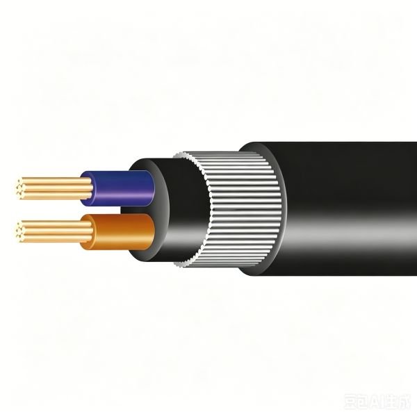
A single-phase 2 × 16 mm² armoured LV feeder: copper conductors to IEC 60228 Class 2, XLPE insulation, galvanised steel wire armour and a black PVC over-sheath. 19 mm overall, 900 kg/km, 115 A in air at 30 °C and 100 A direct buried.
The numbers that decide whether a 2 × 16 mm² armoured feeder suits the route — with the size it sits between, so the step up or down is one glance away.
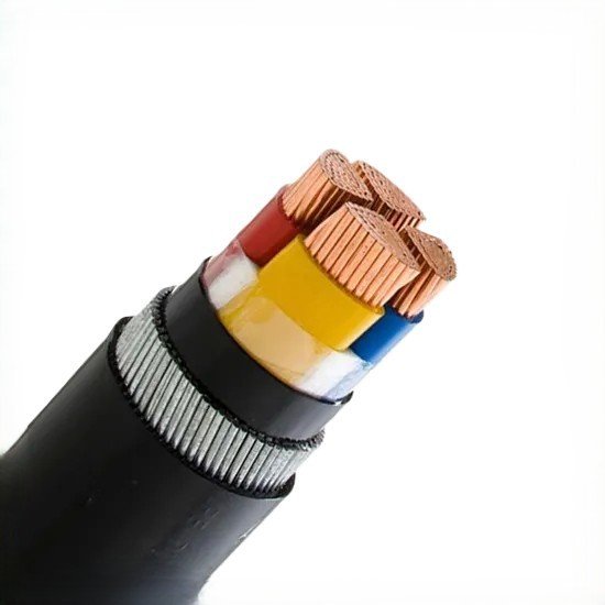
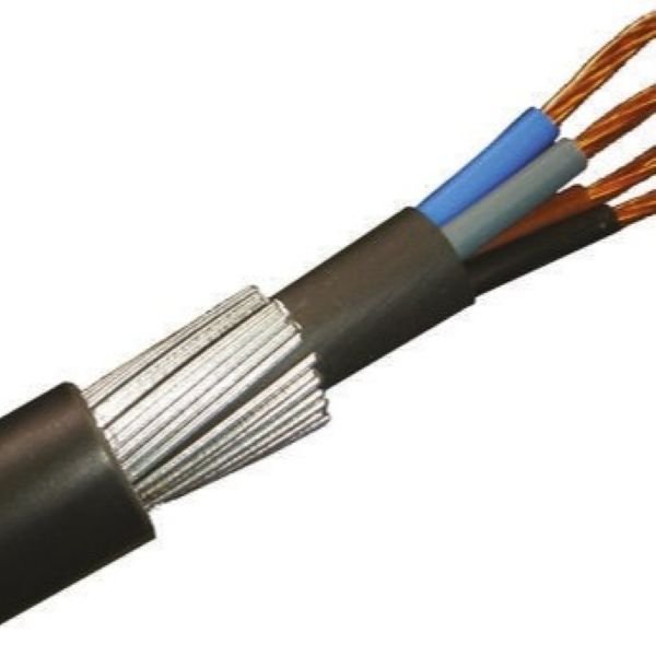
This page is the 2 × 16 mm² member of the BS 5467 armoured LV family: two copper conductors of 16 mm² each, XLPE insulated, laid up with an extruded PVC bedding, armoured with a single layer of galvanised steel wires and finished with a black PVC over-sheath. The published numbers for this exact size are a conductor diameter of 4.8 mm, 0.7 mm of XLPE insulation, 1.25 mm armour wires, a 19 mm overall diameter, a weight of 900 kg/km and a conductor resistance of 1.15 Ω/km at 20 °C.
Two cores means line and neutral, and nothing else. There is no separate protective conductor inside this cable. The steel wire armour can serve as the circuit protective conductor where it is effectively earthed at both ends and the local wiring regulations permit it, and its resistance — 3.7 Ω/km for this size — is the figure that assessment uses. Where a separate PE is required by the project, order 3 × 16 mm² (or a 3 + 1 arrangement) instead of assuming the two-core cable can be made to serve. This is the single most common misunderstanding about two-core armoured cable, and it is worth settling before the order rather than at the joint bay.
The cable is a single-phase feeder: domestic and commercial submains, outbuilding and gate supplies, pump and borehole feeds, and street or site lighting circuits where the run is long enough that 10 mm² would give an unacceptable voltage drop. The step from 2 × 10 mm² (650 kg/km, 17 mm, 86 A in air) to this size is real but modest; the step up to 2 × 25 mm² (1200 kg/km, 23 mm, 149 A in air) is a different drum and a different pull. Table 1 puts the four sizes side by side for exactly that reason.
On installation: the armour is there so the cable can be direct buried or pulled into a duct without a separate conduit system, and so that vehicle loading and rodent activity over a backfilled trench do not end the cable’s service life. At 8 × overall diameter, the laying radius for this size is roughly 152 mm, which is comfortable to achieve by hand in a normal trench — this is the size where armoured LV cable is genuinely easy to install, unlike the larger four-core sections. The armour is not an EMC screen; it is mechanical protection, and specifying it as a screen is a separate discussion.
Everything here comes from the published data for this construction, and it is re-confirmed on the drawing before the drum is made. Where a value is not published — the insulation resistance of the finished length, for example, which is a manufacturer routine-test result — the page says so rather than printing a plausible figure. For the full family including the four-core sections, see the Cu/XLPE/SWA/PVC 0.6/1 kV armoured power cable page.
More about the manufacturer: About SORIVO →
Two 16 mm² copper conductors with a 4.8 mm conductor diameter, XLPE insulated at 0.7 mm, laid up under a PVC bedding.
This is a line-and-neutral cable. Earthing must come from the armour, where the regulations permit it, or from a three-core or 3 + 1 construction ordered instead.
The published armour resistance for this size — the figure an earth-fault loop or armour continuity assessment actually needs.
One of the practical advantages of a two-core armoured cable: a 19 mm cable glands easily, bends by hand and fits standard LV glands and cleats.
Rated for direct burial and for pulling into duct. The steel wire armour is what makes backfill loading and rodent activity survivable.
Published at two reference conditions — in air at 30 °C and direct buried at 20 °C. The buried figure is 13 % lower, and your route decides which one applies.
The conductor resistance for voltage-drop work, remembering that it rises by roughly 20 % at the 90 °C conductor temperature.
Every completed length is withstand-tested at 3.5 kV AC for five minutes, with conductor resistance recorded against the drum.
Single-phase feeders that have to go underground or through a route that will not stay tidy.
A single-phase submains run from a house or main board to a garage, workshop or outbuilding, buried in a trench at a length where 10 mm² would drop too much voltage.
Supplies to electric gates, barriers and driveway lighting where the route crosses ground that gets driven over and the cable must be armoured for the load.
Single-phase feeds to pumps and boreholes, buried or ducted, where a 2-core armoured cable is the standard choice and the earth path is taken from the armour.
Column and pole lighting circuits fed from a single-phase supply, direct buried along the run and glanded into the base compartment.
Single-phase distribution where the cable is laid on the ground, walked on and driven over for the duration of a project and then recovered.
Retail, workshop and light-industrial unit supplies fed single-phase from a landlord’s board, sized where the run length rules out a smaller section.
Sheds, stock buildings and remote equipment where the cable is direct buried across open ground and rodent damage is a real maintenance risk.
Single-phase generator connections and changeover supplies where the run is fixed, buried and needs mechanical protection rather than a flexible cord.
The complete parameter set — the same data our engineers quote from.
| Cores × size (mm²) | Conductor dia. (mm) | Insulation (mm) | Bedding (mm) | Steel wire dia. (mm) | Overall dia. (mm) | Weight (kg/km) | R20 (Ω/km) | In air 30 °C (A) | Buried 20 °C (A) |
|---|---|---|---|---|---|---|---|---|---|
| 2 × 10 | 3.8 | 0.7 | 0.8 | 0.9 | 17 | 650 | 1.83 | 86 | 77 |
| 2 × 16 | 4.8 | 0.7 | 0.8 | 1.25 | 19 | 900 | 1.15 | 115 | 100 |
| 2 × 25 | 5.9 | 0.9 | 0.8 | 1.25 | 23 | 1200 | 0.727 | 149 | 129 |
| 2 × 35 | 6.9 | 0.9 | 1.0 | 1.6 | 26 | 1700 | 0.524 | 185 | 155 |
The neighbouring two-core sizes are shown so the step from 2 × 10 mm² to 2 × 35 mm² is visible in one place: 650 kg/km and 17 mm at 2 × 10 mm², 900 kg/km and 19 mm at 2 × 16 mm², 1700 kg/km and 26 mm at 2 × 35 mm². The 2 × 16 mm² row is highlighted. Overall diameter, weight and current ratings are nominal manufacturer values for this construction, not guaranteed limits, and the current-rating columns are the two manufacturer reference conditions — in air at 30 °C and direct buried at 20 °C — rather than a single "rated current".
| General Information | |
| Product Name | 0.6/1 kV Cu/XLPE/SWA/PVC 16 mm² 2-Core Armoured Power Cable |
| Product Family | Two-core copper conductor, XLPE insulated, steel wire armoured, PVC sheathed low-voltage power cable to BS 5467 |
| Reference Standards | BS 5467; IEC 60502 for the 0.6/1 kV extruded-insulation construction; conductor to IEC 60228 Class 2; flame retardance to IEC 60332-1-2. |
| Rated Voltage U₀/U | 0.6/1 kV |
| Core Configuration | 2 cores — line and neutral. There is no separate protective conductor in this construction; a separate PE requires a 3-core or 3 + 1 arrangement. |
| Dimensional Data (this size) | |
| Conductor Cross-Section | 2 × 16 mm² |
| Conductor Diameter | 4.8 mm |
| Conductor Shape | Circular stranded (RM), Class 2 |
| Insulation Thickness | 0.7 mm nominal |
| Bedding Thickness | 0.8 mm nominal |
| Armour Wire Diameter | 1.25 mm nominal |
| Overall Diameter | 19 mm nominal |
| Approximate Weight | 900 kg/km |
| Electrical Ratings (this size) | |
| Conductor Resistance at 20 °C | 1.15 Ω/km |
| Armour Resistance at 20 °C | 3.7 Ω/km |
| Current Rating, in Air 30 °C | 115 A |
| Current Rating, Direct Buried 20 °C | 100 A |
| Max. Conductor Temperature | +90 °C continuous, the XLPE rating |
| Short-Circuit Conductor Temperature | +250 °C maximum, taken as the IEC 60502-1 short-circuit condition for XLPE-insulated copper cable, limited to 5 s |
| Test Voltage | 3.5 kV AC for 5 minutes on the completed cable |
| Insulation Resistance | Manufacturer routine-test value, confirmed against the report for the supplied drum |
| Voltage Drop | Approximately 2 × 1.15 Ω/km = 2.3 Ω/km for a single-phase circuit at 20 °C. Correct the resistance to the operating temperature and add the reactance term before using it for a final design. |
| Construction | |
| Conductor | Plain annealed copper, Class 2 stranded to IEC 60228 |
| Insulation | Extruded XLPE, 0.7 mm nominal |
| Core Identification | Blue and brown, confirmed against the drawing for the ordered construction |
| Bedding | Extruded PVC over the laid-up cores |
| Armour | Single layer galvanised steel wires, 1.25 mm nominal diameter |
| Outer Sheath | PVC, black |
| Environment | |
| Operating Temperature Range | −20 °C to +90 °C — the range published for this construction |
| Minimum Installation Temperature | 0 °C. Below this the PVC bedding and sheath stiffen; warm the drum area or postpone the pull rather than forcing the cable. |
| Bending Radius when Laying | 8 × overall diameter, the manufacturer figure for this construction. The final radius should be confirmed against the applicable standard and the actual installation method. |
| Weather Resistance | Rated good for outdoor and buried service by the manufacturer data sheet. |
| Flame Retardance | IEC 60332-1-2 — single insulated cable vertical flame propagation |
| Rodent and Termite | The steel wire armour is the barrier. It is a mechanical layer, not a chemical one, so it resists gnawing rather than repelling it. |
| Configuration & Logistics | |
| Standard Lengths | 100 m / 500 m / 1000 m per drum; cut lengths on request |
| Packaging | Wooden drum, coil or custom packaging |
| Customization | Sheath colour, cut length, drum type and customer marking |
| Halogen-Free Variant | The same size is available with a BS 6724 halogen-free sheath — quoted on request |
| MOQ | 500 m — sample orders accepted |
| Lead Time | 7–15 working days |
Every dimensional and electrical value in Table 2 is the published nominal data for this 2 × 16 mm² construction, not a value interpolated from another size: 4.8 mm conductor, 0.7 mm XLPE, 0.8 mm bedding, 1.25 mm armour wires, 19 mm overall, 900 kg/km, 1.15 Ω/km conductor resistance and 3.7 Ω/km armour resistance, with 115 A in air at 30 °C and 100 A direct buried at 20 °C. There is no separate protective conductor in a two-core cable, so the earth path has to come from the armour — where the applicable wiring regulations permit it and the fault-current assessment supports it — or from a three-core or 3 + 1 construction ordered instead. The +250 °C short-circuit figure is a 5-second design condition from the IEC 60502-1 basis for XLPE-insulated copper cable, not a service temperature. Diameters and weights are nominal and re-confirmed on the drawing before production; final selection should be based on the installation method, the ambient conditions and the applicable local requirements.
The construction — copper to IEC 60228, XLPE insulation, galvanised steel wire armour and PVC over-sheath — is the BS 5467 arrangement for 0.6/1 kV armoured cable. We quote the standard the cable is built and tested to; we do not write "certified" where the correct statement is "made to". The test certificate and conductor-resistance records for the supplied drum come with the quotation.
Request the test documents →A 3.5 kV AC withstand test for 5 minutes is applied to every completed length and recorded, and the XLPE insulation and PVC sheath are type-tested as a system for the 0.6/1 kV rating. If you need the type-test report for the exact construction you are buying, ask for it by the ordered size and we will send the one that matches.
Request the type-test report →There is no CE certification for cable — CE marking is a manufacturer’s declaration of conformity, and which directive applies depends on the installation. We will not print "CE certified": a Declaration of Conformity and a RoHS declaration are provided on request for the construction supplied, together with whatever national approval documentation the destination market requires.
Request documentation →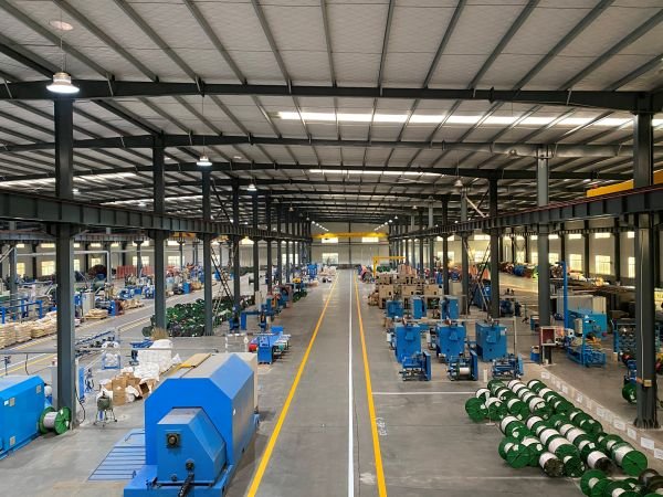
For a single size, the release checks are the ones that decide whether the drum that arrives matches the drawing you approved.
Tell us the quantity and the length per drum, the installation route, and whether a separate protective conductor or a halogen-free sheath is required.
We confirm the length per drum, the sheath type and whether you need a separate PE, send the drawing for a 19 mm / 900 kg/km construction for approval, and quote against it — normally within one working day.
Sample for qualification — stocked configurations within a few working days.
Made-to-order lengths for this size run on a short production window — the exact dates are confirmed in the quotation once the drum schedule and quantity are fixed.
Drum schedule and shipping documents, plus gland and bending-radius guidance for a 19 mm armoured cable and the routine-test records for the supplied drums.
Tell us the run length, the load and the quantity — we reply within one working day.
The more detail you give, the faster and more accurate our quotation. Our engineers reply within one working day.
Thanks — our engineers will reply within one working day.