Professional cable manufacturer

Professional cable manufacturer
Cable Sizing · 2026-06-17
Ampacity does not scale with cross-section. Per IEC 60364-5-52 Table B.52.5, a 2.5 mm² XLPE copper cable with three loaded conductors is rated 30 A clipped direct (Method C, 30 °C air) and 30 A direct buried (Method D2, 20 °C ground); the same size in PVC, Table B.52.4, is 24 A. Across the table, doubling the cross-section raises ampacity by only about 50 % to 56 % — an exponent near 0.62, so ampacity scales as mm²^0.6, not mm²^1.0. Below are the Annex B charts for copper and aluminium, the ambient and grouping derating factors, and a worked 180 A example on a perforated tray at 40 °C.
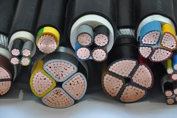
Most sizing mistakes on low-voltage power circuits come from one intuition: that a cable twice as thick carries twice the current. It does not. Across IEC 60364-5-52 Table B.52.5, doubling the cross-section raises the rating by roughly 50 % to 56 % — never 100 %.
Fitting every row of IEC 60364-5-52 Table B.52.5 (XLPE, three loaded conductors, copper, installation Method C) gives an exponent of about 0.62: ampacity scales as roughly mm²0.6, not mm²1.0. The commercial consequence is that doubling a circuit's current takes about three times the copper, not twice.
Table 1 derives that exponent directly from the standard's own published values. Every pair below uses two sizes that appear in Table B.52.5, so you can check each row yourself rather than taking our word for it.
| Size pair (mm²) | Area ratio | Current (A) | Current ratio | Implied exponent |
|---|---|---|---|---|
| 25 → 50 | 2.00 | 119 → 179 | 1.50 | 0.59 |
| 35 → 70 | 2.00 | 147 → 229 | 1.56 | 0.64 |
| 70 → 150 | 2.14 | 229 → 371 | 1.62 | 0.63 |
| 95 → 185 | 1.95 | 278 → 424 | 1.53 | 0.63 |
| 120 → 240 | 2.00 | 322 → 500 | 1.55 | 0.63 |
| 150 → 300 | 2.00 | 371 → 576 | 1.55 | 0.63 |
| 10 → 300 | 30.0 | 71 → 576 | 8.11 | 0.62 |
| 1.5 → 300 | 200 | 22 → 576 | 26.2 | 0.62 |
Exponent = ln(current ratio) ÷ ln(area ratio). Source values: IEC 60364-5-52 Table B.52.5, three loaded conductors, copper, installation Method C (clipped direct), 30 °C air.
The reason is visible in the IEC 60287-1-1 rating equation. In its steady-state form for a buried or air-installed cable:
I = √[ ( Δθ − Wd(0.5 T1 + n(T2+T3+T4)) ) ÷ ( R T1 + n R(1+λ1)T2 + n R(1+λ1+λ2)(T3+T4) ) ]
Every term that matters here works against you as the cable grows. R, the conductor resistance, falls roughly in proportion to cross-section, so I rises as about √A. But T1, the thermal resistance between conductor and sheath, has a logarithm in it — T1 = (ρT/2π) G — so it barely improves as the conductor gets fatter. The heat has to travel through more insulation, not less.
What saves you slightly is T4, the resistance from the cable surface to the surrounding medium. A bigger cable has a bigger surface, so it does shed heat better. That is why the observed exponent, 0.62, sits a little above the √A floor of 0.5 rather than below it.
At an exponent of 0.62, doubling the current requires 21/0.62 ≈ 3.05 times the cross-section. Check it against the table: 1.5 mm² is rated 22 A, and reaching 44 A takes about 4.6 mm² — the next available sizes are 4 mm² (40 A) and 6 mm² (52 A). You are buying three times the copper, not two. On long feeder runs this is where budgets disappear, which is why we treat copper quantity as a priced input rather than a fixed one in our how copper price movement is handled in cable quoting.
Annex B of IEC 60364-5-52 is the source most of the world sizes from. The two tables you will use most are Table B.52.4 (PVC insulation, 70 °C conductor) and Table B.52.5 (XLPE or EPR insulation, 90 °C conductor), both for three loaded copper or aluminium conductors. Table 2 below reproduces the copper columns.
| mm² | XLPE B1 conduit on wall | XLPE C clipped direct | XLPE D2 direct buried | PVC C clipped direct | PVC D2 direct buried |
|---|---|---|---|---|---|
| 1.5 | 20 | 22 | 23 | 17.5 | 19 |
| 2.5 | 28 | 30 | 30 | 24 | 24 |
| 4 | 37 | 40 | 39 | 32 | 33 |
| 6 | 48 | 52 | 49 | 41 | 41 |
| 10 | 66 | 71 | 65 | 57 | 54 |
| 16 | 88 | 96 | 84 | 76 | 70 |
| 25 | 117 | 119 | 107 | 96 | 92 |
| 35 | 144 | 147 | 129 | 119 | 110 |
| 50 | 175 | 179 | 153 | 144 | 130 |
| 70 | 222 | 229 | 188 | 184 | 162 |
| 95 | 269 | 278 | 226 | 223 | 193 |
| 120 | 312 | 322 | 257 | 259 | 220 |
| 150 | 342 | 371 | 287 | 299 | 246 |
| 185 | 384 | 424 | 324 | 341 | 278 |
| 240 | 450 | 500 | 375 | 403 | 320 |
| 300 | 514 | 576 | 419 | 464 | 359 |
Source: IEC 60364-5-52:2009+AMD1:2024 CSV, Annex B, Tables B.52.4 and B.52.5, three loaded conductors, copper. Reference conditions: 30 °C ambient air, 20 °C ground, soil thermal resistivity 2.5 K·m/W, one circuit. Method B1 = multicore cable in conduit on a wall; Method C = clipped direct; Method D2 = directly buried. No grouping or ambient correction applied.
Every number in Table 2 is conditional. Five conditions sit behind them, and if your site differs on any one you must correct:
Method D1 (in ducts in the ground) is deliberately absent from Table 2 because it needs its own column. Ducting adds an air gap in the thermal path, so D1 ratings sit below D2 for the same size above about 25 mm² — at 300 mm² XLPE the difference is 365 A against 419 A, about 13 %. We cover installation-method comparisons in detail in cable ampacity by installation method.
The question we are asked most often is not "which is better" but "what size do I buy instead". Table 3 answers it from the same Annex B data, by interpolating the aluminium column to find the cross-section that delivers the same current as each copper size.
| Copper mm² | Copper A | Aluminium mm² needed | Ratio | Nearest standard size up | Sizes up |
|---|---|---|---|---|---|
| 16 | 96 | 27.6 | 1.73 | 35 | 2 |
| 25 | 119 | 39.1 | 1.57 | 50 | 2 |
| 35 | 147 | 55.7 | 1.59 | 70 | 2 |
| 50 | 179 | 73.2 | 1.46 | 95 | 2 |
| 70 | 229 | 108 | 1.54 | 120 | 2 |
| 95 | 278 | 146 | 1.53 | 150 | 2 |
| 120 | 322 | 185 | 1.54 | 185 | 2 |
| 150 | 371 | 229 | 1.53 | 240 | 2 |
| 185 | 424 | 283 | 1.53 | 300 | 2 |
| 240 | 500 | > 300 | — | outside B.52.5 range | — |
Aluminium values log-interpolated from IEC 60364-5-52 Table B.52.5 aluminium column, Method C. "Sizes up" counts steps in the standard size series 1.5 / 2.5 / 4 / 6 / 10 / 16 / 25 / 35 / 50 / 70 / 95 / 120 / 150 / 185 / 240 / 300. At 240 mm² copper the required aluminium section exceeds the largest size tabulated in B.52.5, so we did not extrapolate.
The pattern is remarkably stable: between 50 and 185 mm² copper, aluminium needs about 1.5 times the cross-section, which works out to two standard sizes up almost every time. Below 16 mm² the ratio widens to about 1.7, which is why small aluminium conductors rarely make sense.
Our own YJV/YJLV datasheet lists maximum DC resistance at 20 °C of ≤ 0.124 Ω/km for copper and ≤ 0.200 Ω/km for aluminium at 120 mm² — a ratio of 1.61. The table-derived ratio at that size is 1.54. The gap is real and instructive: if equal heating were the only criterion, the aluminium section would have to match the resistance ratio at 1.61. It comes in lower because the larger aluminium conductor also has more surface area to shed heat from.
That is the whole trade in one line. Aluminium needs more section, but not as much more as the resistance ratio alone suggests. Whether the larger, lighter, cheaper conductor wins on your project depends on tray fill, bending radius, termination hardware and lugging practice — not on the ampacity table. We go through those in copper versus aluminium in practice and in the total cost of ownership guide.
The tabulated value is the starting point, never the answer. Three corrections cover most real projects, and they multiply.
For air installations the correction follows directly from the thermal model, and you can compute it rather than look it up:
f = √[ (θc − θa) ÷ (θc − 30) ]
where θc is the maximum conductor temperature and θa your ambient. For XLPE at 40 °C this gives √(50/60) = 0.913, which matches the 0.91 published in IEC 60364-5-52 Table B.52.14. For PVC at 40 °C it gives √(30/40) = 0.866 against a tabulated 0.87. If your ambient is 50 °C, XLPE falls to 0.82 and PVC to 0.71 — the point where PVC stops being viable for a heavily loaded circuit. High-ambient design has its own failure modes, covered in our derating guide for temperature, altitude and grouping.
This is the correction people forget, and it is often the largest. Table B.52.17 gives reduction factors by arrangement and circuit count. The spread between arrangements is far wider than most engineers assume.
| Arrangement (cables touching) | 1 | 2 | 3 | 4 | 5 | 6 | 7 | 8 | 9 |
|---|---|---|---|---|---|---|---|---|---|
| Bunched in air, on a surface, embedded or enclosed | 1.00 | 0.80 | 0.70 | 0.65 | 0.60 | 0.57 | 0.54 | 0.52 | 0.50 |
| Single layer on wall, floor or unperforated tray | 1.00 | 0.85 | 0.79 | 0.75 | 0.73 | 0.72 | 0.72 | 0.71 | 0.70 |
| Single layer directly under a wooden ceiling | 0.95 | 0.81 | 0.72 | 0.68 | 0.66 | 0.64 | 0.63 | 0.62 | 0.61 |
| Single layer on a perforated horizontal or vertical tray | 1.00 | 0.88 | 0.82 | 0.77 | 0.75 | 0.73 | 0.73 | 0.72 | 0.72 |
| Single layer on ladder support or cleats | 1.00 | 0.87 | 0.82 | 0.80 | 0.80 | 0.79 | 0.79 | 0.78 | 0.78 |
Source: IEC 60364-5-52 Table B.52.17, to be used with the ratings in Tables B.52.2 to B.52.13. For bunched cables the series continues to 0.45 at 12 circuits, 0.41 at 16 and 0.38 at 20. For the four single-layer arrangements the standard states there is no further reduction beyond nine circuits.
The practical lesson is in the first two rows. Six circuits bunched together lose 43 % of the rating. The same six cables laid in a single layer on a perforated tray lose only 27 %. Spacing is not cosmetic — it is capacity you have already paid for. Buried grouping behaves differently again because soil, not air, is the heat sink; see burial spacing and derating.
For buried circuits the 2.5 K·m/W reference is a convention, not a measurement. Dried sand can sit well above 3.0 K·m/W and moisture-retentive clay below 1.0, which moves the rating in opposite directions by more than the usual safety margins. Because this variable dominates buried designs and deserves its own treatment, we keep it out of this page and point you to soil thermal resistivity and buried ampacity.
Here is the full sequence on a realistic circuit, using nothing but the tables above.
The circuit. Three-phase, 400 V, design current Ib = 180 A. Multicore XLPE copper cable, single layer on a perforated horizontal tray together with five other circuits (six in total, touching), ambient air 40 °C.
Step 1 — collect the correction factors. Ambient: XLPE at 40 °C gives 0.91 (Table B.52.14; the √ formula returns 0.913). Grouping: six circuits, single layer on a perforated tray, Table B.52.17 row 4 gives 0.73. No soil factor applies — this route is in air.
Step 2 — combine them. 0.91 × 0.73 = 0.664. This is the single number most sizing errors come from: the corrections multiply, they do not add.
Step 3 — find the required tabulated rating. The installed rating must be at least Ib, so the tabulated value must satisfy Iz × 0.664 ≥ 180 A, i.e. Iz ≥ 271 A.
Step 4 — read the table. From Table 2, Method C, XLPE: 70 mm² gives 229 A, which fails. 95 mm² gives 278 A, which passes with a little margin. The answer is 95 mm².
Note what happened. Without derating, 180 A would have been met by 50 mm² (179 A) — right on the line. With realistic site conditions the same circuit needs 95 mm², two sizes larger. That is not conservatism; it is what the standard actually requires once you stop assuming a single cable in 30 °C air.
Step 5 — voltage drop, which is a separate limit. Ampacity tells you the cable will not overheat. It does not tell you the equipment will see usable voltage. For a three-phase run the drop is approximately ΔU = √3 × I × L × (R cosφ + X sinφ), and you need R and X from the datasheet of the specific cable you are buying. We deliberately do not publish a generic resistance table here: values shift with stranding, compaction and armour, and a resistance table that is one row out has caused real specification errors before. Take the numbers from your datasheet, then run them through our cable ampacity calculator or the DC and PV voltage-drop method if the run is long.
IEC 60364-5-52 Clause 525 requires the voltage drop between the origin of the installation and the equipment to be no greater than the value given in the relevant national annex; the standard does not itself fix a universal percentage. The 3 % and 5 % figures quoted in most English-language references come from national implementations and local practice. We treat 5 % here as a design input you choose, not as an IEC value — substitute whatever your project specification and authority require.
If you are sizing to NFPA 70 rather than IEC, the tables are not interchangeable. NEC Table 310.16 works in AWG and kcmil, assumes 30 °C ambient and not more than three current-carrying conductors, and publishes three columns by insulation temperature rating.
| AWG / kcmil | 60 °C TW, UF | 75 °C THW, THWN, XHHW | 90 °C THHN, THWN-2, XHHW-2 |
|---|---|---|---|
| 14 | 15 | 20 | 25 |
| 12 | 20 | 25 | 30 |
| 10 | 30 | 35 | 40 |
| 8 | 40 | 50 | 55 |
| 6 | 55 | 65 | 75 |
| 4 | 70 | 85 | 95 |
| 3 | 85 | 100 | 115 |
| 2 | 95 | 115 | 130 |
| 1 | 110 | 130 | 145 |
| 1/0 | 125 | 150 | 170 |
| 2/0 | 145 | 175 | 195 |
| 3/0 | 165 | 200 | 225 |
| 4/0 | 195 | 230 | 260 |
| 250 | 215 | 255 | 290 |
| 300 | 240 | 285 | 320 |
| 350 | 260 | 310 | 350 |
| 400 | 280 | 335 | 380 |
| 500 | 320 | 380 | 430 |
Source: NFPA 70 (NEC) Table 310.16, copper conductors, 30 °C ambient, not more than three current-carrying conductors in raceway, cable or earth. One reference lists 150 A for 1 AWG at 90 °C where the ICC reproduction and two others list 145 A; we have used 145 A. Verify against the edition adopted in your jurisdiction.
That 90 °C column is the conductor's own thermal limit, not the circuit's. NEC 110.14(C)(1) requires the ampacity to be selected using the lowest temperature rating of any termination, conductor or device in the circuit. A 12 AWG THHN conductor is listed at 30 A in the 90 °C column, but if the breaker it lands on is rated 75 °C you size from the 75 °C column — 25 A — and then apply the continuous-load rule. The 90 °C value is still useful: it is the correct starting point when you apply ambient or conductor-count derating, before comparing the result against the terminal limit.
Because NEC sizing pulls in termination ratings, continuous-load factors and conductor-count adjustment, it warrants its own treatment. See what THHN wire is under UL 83 for the conductor-type side of that decision, and what changed between NEC 2023 and NEC 2026 if your project straddles both code cycles.
If you have compared an IEC table against a manufacturer's ampacity chart and found the manufacturer's numbers higher, you have not found an error. You have found the difference between a generic model and a measured construction. But you should know how large that difference is before you mix sources.
We checked the chart that previously appeared on this page — compiled from manufacturer selection data — against IEC 60364-5-52 Table B.52.5, Method C, XLPE copper:
| mm² | Catalogue chart | IEC B.52.5 | Difference |
|---|---|---|---|
| 1.5 | 23 | 22 | +4.5 % |
| 2.5 | 31 | 30 | +3.3 % |
| 4 | 42 | 40 | +5.0 % |
| 6 | 54 | 52 | +3.8 % |
| 10 | 75 | 71 | +5.6 % |
| 16 | 100 | 96 | +4.2 % |
| 25 | 133 | 119 | +11.8 % |
| 35 | 164 | 147 | +11.6 % |
| 50 | 198 | 179 | +10.6 % |
| 70 | 253 | 229 | +10.5 % |
| 95 | 310 | 278 | +11.5 % |
| 120 | 355 | 322 | +10.2 % |
| 150 | 400 | 371 | +7.8 % |
| 185 | 455 | 424 | +7.3 % |
| 240 | 536 | 500 | +7.2 % |
| 300 | 610 | 576 | +5.9 % |
Catalogue column: values as published on this page between 2026-06-17 and 2026-09-10, sourced from manufacturer selection tables. IEC column: Table B.52.5, three loaded copper conductors, Method C.
The gap ranges from 3 % to 12 %, and it is widest — 10 % to 12 % — exactly in the 25 to 120 mm² band where most distribution feeders are sized. Both sets of numbers can be legitimate: a catalogue value reflects a specific, tested construction, and a well-made cable with a compacted conductor and good bedding genuinely dissipates heat better than the generic model behind Annex B.
The previous version of this page published the catalogue-derived column in Table 6 as its primary chart. It ran 3 %–12 % above IEC 60364-5-52 Annex B, and a reader who took a catalogue base value and then applied IEC derating factors would have been mixing two different bases. This version uses Annex B throughout. The one rule that matters: choose your base — standard or manufacturer — and apply that source's own correction factors. Never cross them.
Before the cable goes on the drum, these are the checks that catch the expensive mistakes. They assume you have already selected a size using the method in section 05.
For a specific circuit, run the numbers in our cable ampacity calculator. For the analytical method behind the tables, including when Annex B is not enough, see IEC 60287 ampacity calculation. If your cable is rated higher on paper than it performs on site, the gap is usually diagnosed in rated current versus actual current.
We have reproduced IEC 60364-5-52 Annex B values for Tables B.52.4, B.52.5 and B.52.17, derived the scaling exponent from those tables rather than asserting it, and given a reproducible aluminium equivalence. The NEC section is included for North American work and is deliberately kept separate, because the two systems do not convert.
We have not published a conductor resistance or reactance table, because the values are construction-specific and a misaligned row is a genuine hazard. We have not stated a universal voltage-drop percentage, because IEC 60364-5-52 refers that to the relevant national annex. And we have not given cost figures, because cable pricing moves with copper and a static number would be wrong before it is read.
Where a value in the source material conflicted — the 1 AWG 90 °C column being the clearest example — we have said so and told you which figure we adopted. Where we could not verify a claim, including a "400 mm² versus 185 mm²" comparison that appeared on an earlier version of this page, we removed it rather than defend it.
Send us the load current, route and installation method, ambient temperature, number of circuits in the group, run length and whether the conductor is copper or aluminium. We will come back with the IEC 60364-5-52 section we sized from, the derating factors applied, and the resulting cross-section — including where a size change would change the answer.

Per IEC 60364-5-52 Table B.52.5, a 2.5 mm² XLPE copper cable with three loaded conductors is rated 30 A clipped direct (Method C, 30 °C air) and 30 A direct buried (Method D2, 20 °C ground). The same size in PVC, Table B.52.4, drops to 24 A in both. Derating applies for higher ambient temperature and for grouping.
No. Across IEC 60364-5-52 Table B.52.5, doubling the cross-section raises ampacity by only about 50 % to 56 %. Fitting the whole table gives an exponent of roughly 0.62: ampacity scales as mm²0.6, not mm²1.0. The practical consequence is that doubling a circuit's current takes about three times the copper, not twice.
For equal ampacity on Method C, IEC 60364-5-52 Tables B.52.4 and B.52.5 show aluminium needs roughly 1.5 to 1.6 times the cross-section between 50 and 240 mm². In practice that means two standard sizes up: 50 mm² copper, rated 179 A, is matched by 95 mm² aluminium at 174 A. Below 16 mm² the ratio widens to about 1.7.
Table B.52.17 gives 0.73 for six circuits in a single layer on a perforated horizontal or vertical tray. The same six cables bunched on a surface drop to 0.57. Combine it with the ambient factor: at 40 °C with XLPE, 0.91 × 0.73 = 0.66, so the tabulated rating must be at least 1.5 times the load current.
Catalogue values are measured or calculated for a specific construction, which often dissipates heat better than the generic model behind IEC 60364-5-52 Annex B. We compared one such chart against Table B.52.5 and found it 3 % to 12 % higher, widest at 25 to 120 mm². Both can be correct; the error is mixing a catalogue base with IEC derating factors.
No. NEC Table 310.16 gives allowable ampacities for AWG and kcmil sizes at 30 °C with not more than three current-carrying conductors, in 60, 75 and 90 °C columns. IEC 60364-5-52 Annex B uses mm² sizes and installation method codes A1 to G. Do not convert between them by rounding; size each system on its own table.
How this was written: every figure in this article is checked against the standard or regulation listed in Sources before publication. Where a value is our own measurement, it is labelled as such.